
Carbon Felt Insulation for High-Temperature Vacuum Furnaces
Study thickness and heat loss, compare material evidence and prepare your furnace RFQ.
Published and sources reviewed: November 1, 2026 · English technical guide
Published by SiC Crystal Crucibles. Review due May 2027, or earlier if supplier data or standards change.
Request engineering reviewInteractive sizing study · instant results
Carbon felt thickness & heat loss calculator
Compare thickness and heat loss. Example values are assumptions, not supplier data.
1000–2400°C; interface range is not a grade rating.
0–500°C; an assumed boundary, not shell safety.
0.01–10; match grade, gas, pressure, density and heat-flow direction.
1–2000 mm after installation/compression.
0.01–1000 m²; cylinders need a radial model.
0–8784 h; excludes ramps and cooling.
0.05–100; your study target, not an industry limit.
User data is not independently verified here.
Changing gas does not correct k. Enter matching data before comparing results. All * fields are required.
Illustrative estimate · assumptions only
Heat flux
8.7 kW/m²
Insulation thermal loss
21.32 kW
Annual thermal loss
127,890 kWh
Model target thickness
376.22 mm
Above your heat-flux target: review thickness or boundary assumptions.
Rounded up to 10 mm: 380 mm. This is a study increment, not a stock size or released design.
Target needs more than 160 mm in this model. The result has not been capped; check available space and redesign options with the furnace engineer.
Cold face is an input. Shell temperature, safe touch limits, cooling demand and product suitability are not calculated.
Assumes constant effective k and steady one-dimensional planar flow. Seams, fasteners, curvature, load and quench flow are excluded. Annual output is thermal energy at the entered conditions, not an electricity bill.
View / manually copy study summary
No conductivity data? Use the example for sensitivity only and request grade-specific k(T), pressure and test details. See method & limits.
1. Four decisions before choosing furnace felt
Choose an exact grade. Carbonized and graphitized materials have different processing histories. Confirm the supplier operating envelope rather than using the precursor as a temperature rating. Material basis
Match thermal test conditions. Gas and vacuum values differ even for one rigid grade. A vacuum k value cannot represent an arbitrary gas process. Grade-specific example
Separate purity from thermal performance. Purification and facing are specification choices, not automatic conductivity discounts. Request batch evidence. Supplier options
Specify how properties were tested. Method, specimen and atmosphere determine whether conductivity values are comparable. A calculator output is not laboratory validation. C177 scope / E1461 scope
2. Carbonized, graphitized, rayon and PAN: separate the variables
SGL describes cellulose-derived soft felt carbonization at 800–1000°C and further treatment above 2000°C for its graphite-like soft felts. Those are processing descriptions, not universal service limits. SGL material explanation
Mersen describes CBCF as short rayon-derived fibers joined by a carbonized resin matrix, and offers both soft graphite felt and purification options. These product families illustrate why precursor, heat treatment, form and purity must be separate RFQ fields. Mersen product description
| Variable | What to compare | Evidence to request |
|---|---|---|
| Rayon vs PAN | Exact grade under the same process conditions | Through-thickness k(T), installed density, lot data |
| Carbonized vs graphitized | Processing history and operating envelope | Heat-treatment record, dimensional change after cycling |
| Soft vs rigid CBCF | Geometry, handling and support needs | Drawings, flexural/handling data, facing construction |
| Standard vs purified | Process-specific contamination limits | Elemental analysis, detection limits, batch identification |
3. Calculation method, assumptions and known limits
The tool uses a constant effective conductivity in a steady planar model: q = k × (T hot − T cold) / t, with t in metres for W/m². With t entered in mm, the same numerical expression gives kW/m². Thermal power Q = q × area; annual thermal energy = Q × hours at condition. Target thickness in mm = k × (T hot - T cold) / target q in kW/m².
For k varying only with temperature, the equivalent interval value is k effective = integral[k(T) dT] / (T hot - T cold). It must describe the same gas, pressure, density and heat-flow direction. Using a value measured only at the hot face is an approximation, not an integrated model. The example k = 0.4 W/m·K is an editable assumption, not a quoted product property.
| Item | Tool treatment | What remains to be established |
|---|---|---|
| Temperature and k | User inputs; illustrative defaults are labeled | Actual boundary temperatures and interval-effective k |
| Target thickness | Algebraic result, then rounded upward to 10 mm without a cap | Stock sizes, space, layer interfaces and grade approval |
| Heat loss | Insulation path only, uniform planar area | Seams, supports, penetrations, curvature and heater/load losses |
| Annual energy | Steady thermal loss × entered operating hours | Electrical input, cycle profile, cooling power and tariff |
| Cold face and shell | Cold face is assumed; shell is not calculated | Cooling circuit, contact resistances and shell temperatures |
For a cylindrical wall with constant k, use radial resistance ln(r outer / r inner) / (2 × pi × k × L), plus ends and penetrations separately. A planar area estimate cannot silently substitute for this geometry. Multilayer walls likewise need layer-specific resistances and interface temperatures.
4. Compare measurement methods without invented error bars
C177 addresses steady heat flow through flat specimens; E1461 measures diffusivity, from which conductivity can be derived with density and heat capacity. Their public scopes do not establish a universal percentage difference between methods. C177 / E1461
SGL publishes soft-felt thermal data measured by laser flash. This directly rules out a blanket claim that laser flash is always unsuitable for felt. Request the laboratory treatment of porosity, anisotropy, optical transmission and heat-loss corrections. SGL brochure, pp. 10–11
| Evidence | Ask the supplier or laboratory | Reject an unsupported inference |
|---|---|---|
| Steady-state heat-flow test | Specimen thickness, density, direction, temperatures and atmosphere | A method number alone proves accuracy at 2400°C |
| Flash diffusivity test | Specimen preparation, optical treatment, density, heat capacity, corrections | Every porous sample has the same positive error |
| Any quoted k value | Grade, batch, pressure, gas, uncertainty and date | Vacuum data applies unchanged to gas backfill |
5. A traceable example: atmosphere changes the data
The historical Mersen CBCF 15-2000 sheet gives the following typical values for one rigid grade. It is dated February 2009, not 2026; the review date does not make it current. The table does not specify test pressure or uncertainty, so it illustrates condition dependence and is not used to populate the calculator. Original grade sheet
| Reported temperature | Nitrogen | Vacuum |
|---|---|---|
| 400°C | 0.33 | 0.12 |
| 800°C | 0.48 | 0.18 |
| 1200°C | 0.68 | 0.32 |
| 1600°C | 1.07 | 0.52 |
| 2000°C | 1.24 | 0.83 |
Engineering recommendation: request the actual pressure and gas species with each k(T) curve. Neither the historical points nor an assumed cubic temperature curve resolves an unmeasured operating condition. Do not extrapolate these values to a different precursor or grade.
6. Architecture: insulation, facing and retention do different jobs
Soft felt adapts to shapes; a rigid board or cylinder supports a defined geometry. Mersen lists surface treatments intended to limit gas permeability and erosion-related dust. This supports evaluating a facing, but does not establish a universal jet-velocity rating. Rigid/soft construction and surfaces
| Architecture | Reason to evaluate | Tradeoff / qualification |
|---|---|---|
| Soft felt layers | Curved shapes, cutting and local replacement | Restraint, installed density, seams and handling dust need control |
| Rigid CBCF | Defined segments and repeatable installation | Machining, joints, handling damage and replacement access |
| Hybrid with facing | Separate insulation from surface protection | Extra interfaces, attachment and differential movement |
| All-metal hot zone | Alternative where carbon contamination is unacceptable | Recheck process temperature, atmosphere, cost and thermal design |
For gas quench, specify nozzle direction, local flow, peak pressure, pressure ramp, venting and facing retention. Evaluate quenching separately from static hot hold. Do not release unqualified foil, fastener spacing or washer dimensions based on the calculator.
Discuss your insulation architecture7. Purity, outgassing and semiconductor process fit
Ash residue, individual elements, shed particles and desorbed gases answer different questions. C561 concerns ash and is not intended for determining ash in purified graphite. It cannot be used here as evidence of a boron limit or model validation. ASTM public scope
Mersen describes optional purification for its insulation. The appropriate acceptance limit remains process-specific; no universal boron, aluminum, wafer-yield or outgassing guarantee is established by this page. Supplier purification options
- SiC PVT: agree critical elements, detection limits, batch sampling and vapor-exposure compatibility with the growth-process owner.
- Brazing: qualify the carbon environment against workpiece chemistry, particle tolerance and vacuum requirements.
- Outgassing: request the test temperature, time, sample area, conditioning history, pumping arrangement and measured species; it is not calculable from an ash tier.
8. Risk, commissioning and replacement decisions
Engineering review is required for air ingress, moisture, reactive gases and process vapor exposure. This guide supplies no oxygen partial-pressure threshold that guarantees service life, no universal oxidation rate, and no material-life multiplier.
| Risk or mismatch | Evidence to collect | Minimum response |
|---|---|---|
| Unexpected temperature or power rise | Repeatable load/cycle, wall temperatures and cooling observations | Inspect joints and insulation; compare like-for-like baselines |
| Dust, embrittlement or dimensional change | Photos, retained samples, installed density and cycle history | Contain particles; identify failure mode before replacing like-for-like |
| Air / moisture ingress or reactive gas | Leak checks, gas specification and approved interlocks | Resolve compatibility and leak cause before hot operation |
| Quench erosion or delamination | Facing inspection, flow and pressure-cycle records | OEM review of protection, retention and venting |
| Budget or process mismatch | Installed cost, downtime, scrap and whole-cycle energy | Compare qualified alternatives at equal acceptance criteria |
Commissioning: follow the furnace OEM and selected material supplier procedure for storage, drying, ramp rates, holds, vacuum checks and acceptance. Do not add a generic “100°C above operating temperature” bake-out: material and equipment ratings still apply. Record a baseline before production release.
9. Three reproducible studies, not customer performance claims
All examples below are hypothetical. Common assumptions: planar geometry, hot/cold faces 1800/60°C, area 2.45 m², 6000 h/year at steady conditions and target 1.85 kW/m². The tool scenario buttons reproduce them. No cost, yield or service-life improvement has been measured.
| Study / inputs | Calculated result | Decision / limitation |
|---|---|---|
| A: 80 mm, k = 0.4 W/m·K | 8.70 kW/m²; 21.315 kW; 127,890 kWh/year; target thickness 376.22 mm → 380 mm | Current assumed thickness misses target; check space and k basis |
| B: 120 mm, same k | 5.80 kW/m²; 14.21 kW; 85,260 kWh/year; target thickness unchanged | Thickness change reduces this modeled path only; overall furnace saving is unknown |
| C: 80 mm, k = 0.8 W/m·K | 17.40 kW/m²; 42.63 kW; 255,780 kWh/year; target thickness 752.43 mm → 760 mm | Sensitivity to k doubles modeled loss; this is not a measured gas correction |
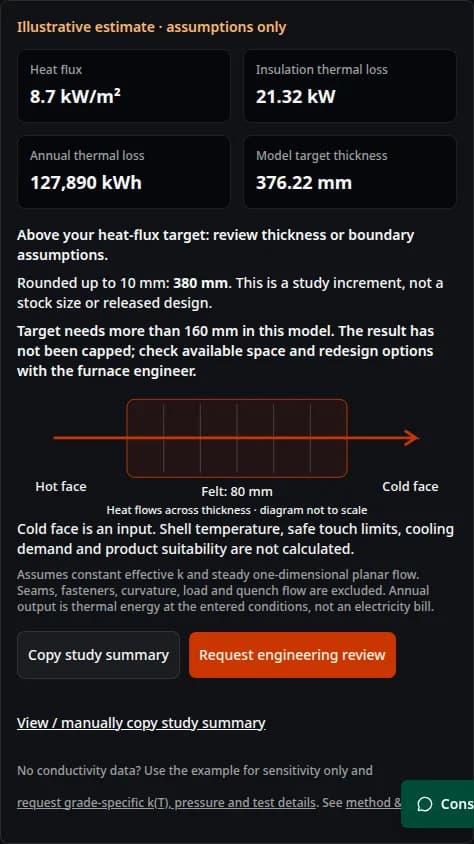
The large calculated thicknesses are useful flags: an arbitrary heat-flux target and a guessed k can be mutually impractical. Confirm measurements and boundaries, consider a different architecture, or revise the target with the designer. A silent 160 mm cap would hide that conflict.
10. Compare lifecycle cost using measured production data
Use total installed cost plus replacements, labor, downtime, qualification and measured cycle energy over a common study period. Compare equal part quality, workload, gas cycle and availability. Model thermal-energy differences only as sensitivity inputs; electricity conversion and tariffs need site data.
Unknown on this page: purchase prices, cycle life, replacement intervals, electricity tariff and yield effect. Request them before making a payback claim. A cheaper felt may increase maintenance or qualification effort; a more expensive facing may also add handling complexity. Neither outcome is assumed.
11. RFQ package: enough information for an engineering decision
Process and geometry
- Drawing: ID, OD, height, flat areas, doors and penetrations.
- Temperature range, ramp, hold time and cycles.
- Gas species, pressure in Pa/bar, static or flowing mode.
- Available insulation space, cooling system and boundary data.
Material and acceptance
- Named grade, treatment history, form, installed density and k(T) test conditions.
- Critical elements, particles, outgassing and test protocols.
- Facing, retention, seams and dimensional acceptance.
- Quantities, delivery country, schedule, current failure evidence.
Copy the study summary above and attach it with these inputs. Missing data should remain “to be confirmed” in the quotation; estimated values should not become guaranteed purchase-order limits.
12. Source ledger and evidence limits
Reviewed November 1, 2026. Dates refer to this review unless a document date is named. Links below are primary manufacturer publications or public standards scopes. No full paid standard, proprietary test report or customer result is claimed to have been audited.
- SGL Carbon — SIGRATHERM soft felt
Carbonized versus graphitized processing; vacuum/inert-atmosphere applications. Does not qualify every felt for 2400°C.
- SGL Carbon — Specialty graphites for high-temperature furnaces
Soft felt discussion on pp. 10–11 includes laser-flash measurements. Manufacturer examples, not proof of a universal precursor ranking.
- Mersen — Rigid and soft carbon insulation
CBCF construction, purification options, surface treatments and graphite soft felt. Published product descriptions are not batch certificates.
- Mersen — CALCARB CBCF 15-2000 datasheet (February 2009)
Historical typical conductivity values in nitrogen and vacuum for this one rigid grade. Pressure and uncertainty are not specified in the table; request current data.
- ASTM C177-19(2026) — Guarded hot plate
Public scope for steady-state flat-specimen heat-flow testing. Apparatus conditions and uncertainty matter; this calculator is not an ASTM test.
- ASTM E1461-13(2022) — Flash method
Public scope for diffusivity measurement; conversion to conductivity needs density and heat capacity. Porous/anisotropic specimens require appropriate experimental design.
- ASTM C561-23 — Ash in graphite
Public scope concerns nonburnable residue and states limits for purified graphite. It does not certify elemental purity or heat-loss calculations.
Evidence gaps: no matched-batch rayon/PAN comparison, furnace-specific oxidation threshold, universal siliconization expansion/stress prediction, outgassing rate, commissioned bake-out schedule or measured ROI is established here. The report therefore makes no numerical guarantee for them. Request process-specific evidence before procurement release.
Frequently asked engineering and sourcing questions
Sizing and model boundaries
What thickness of carbon felt does a high-temperature vacuum furnace need?
There is no universal thickness. Use grade-specific effective conductivity, actual temperature boundaries, available space and an agreed heat-flux target for a preliminary study. Finalize with the furnace designer, including seams, supports, curvature and cooling.
Does this calculator predict the furnace shell temperature?
No. Cold-face temperature is an input, not a prediction. Shell temperature also depends on contacts, wall construction and cooling. The tool does not assess safe touch temperature.
Can I use one hot-point conductivity value as the interval-average k?
Only as an explicitly approximate sensitivity assumption. For temperature-dependent k, use the integral average across the hot-to-cold interval under the same gas, pressure, density and direction, or ask for a layered thermal model.
Can I model a cylindrical hot zone or gas quench?
Use a separate radial model for cylindrical walls. The tool suppresses results for flowing/quench gas because it does not model convective flow. Static operation and quenching must be evaluated separately.
Material, testing and procurement
Is carbonized felt the same as graphitized felt?
No. They undergo different heat treatments. Select an exact grade using its declared processing history and operating envelope. Neither the precursor name nor the interface temperature range proves suitability.
Is rayon always better than PAN carbon felt?
No universal ranking is established here. Compare named grades using conductivity at matching conditions, dimensions, shrinkage, contamination data and total installed cost.
Is laser flash testing always invalid for felt?
No. E1461 describes a diffusivity method with specimen assumptions, while SGL publishes soft-felt laser-flash data. Ask how a laboratory handles porosity, anisotropy, optical effects and heat losses. No fixed error percentage is asserted.
Does a low ash number prove semiconductor compatibility?
No. Agree critical elements, detection limits, sampling and batch traceability separately. ASTM C561 has stated limitations for purified graphites; a small ash value alone does not establish boron or aluminum concentrations.
Operation and next steps
Can bare soft felt face high-speed quench gas?
Do not assume that it can. Have the OEM qualify the facing, retention, venting and erosion resistance against the actual flow field and pressure cycle. No universal velocity or pressure threshold is provided here.
What is a safe oxygen partial pressure or bake-out schedule?
This page does not establish either. Follow the approved furnace and material commissioning procedure, leak checks and interlocks. Do not exceed equipment or material ratings to follow a generic bake-out instruction.
Does the annual thermal-loss estimate equal electrical savings?
No. It covers only the modeled insulation path during hours at the entered steady conditions. Electrical use also includes load heating, ramps, other losses, cooling and system efficiency. Use measured whole-cycle energy for cost decisions.
What if I do not have conductivity or outgassing data?
Use the example only to understand sensitivity. Send drawings, gas species and pressure, operating cycle, contamination limits and current failure symptoms. Ask for grade-specific thermal data and conditioned outgassing measurements before releasing a specification.
Request a furnace insulation review and quotation
Send the study assumptions, drawings and operating conditions. Ask for grade suitability, thermal data, an assembly proposal and explicit acceptance criteria before ordering.
Inquiry Email
Attach DWG, STEP, or PDF drawings and include purity, tolerance, quantity forecast, and delivery country.
Instant Chat
WhatsApp Engineering Support
Use WhatsApp for quick engineering clarification before a formal quote.