
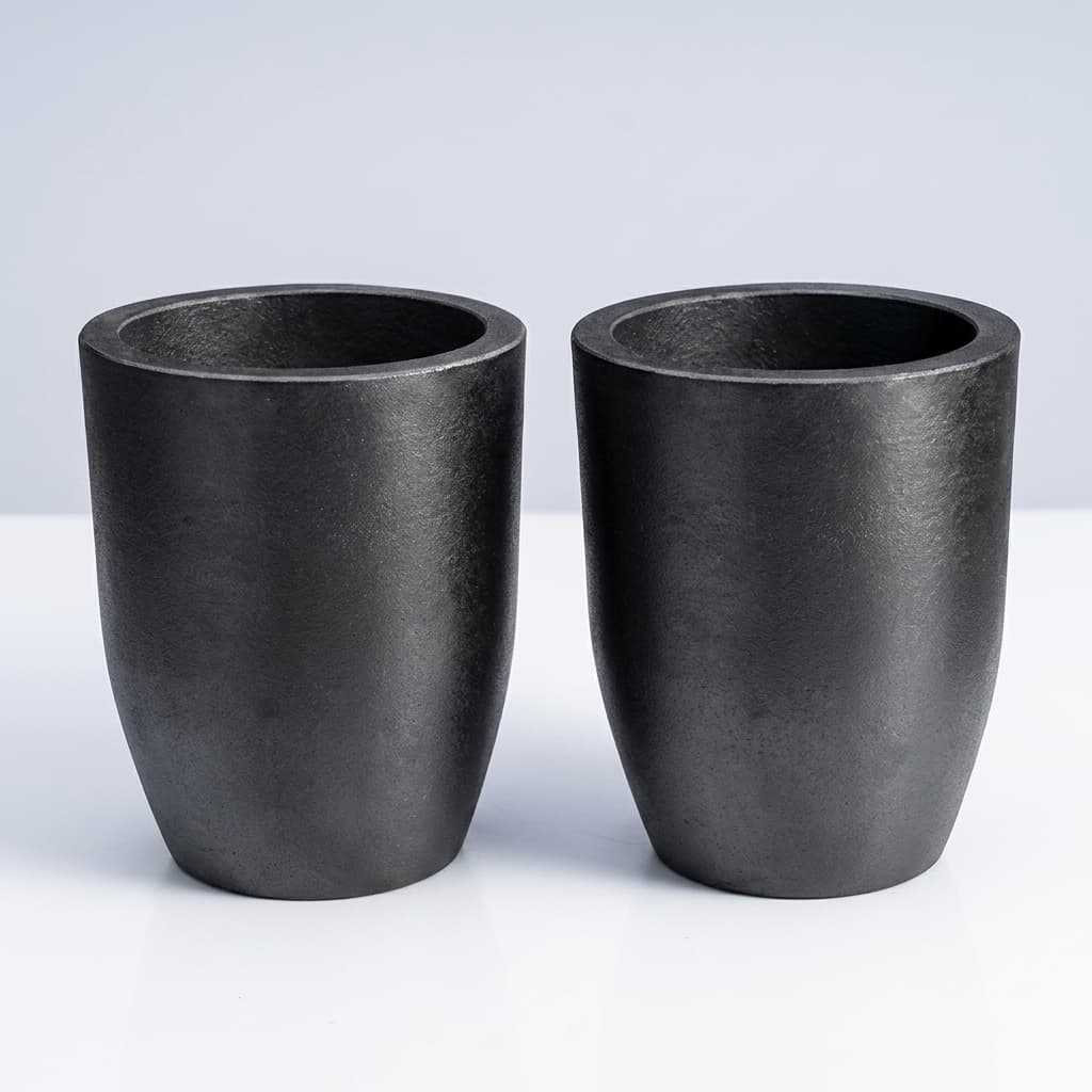
Graphite Crucible Degradation Mechanisms in SiC PVT Growth: Silicon Vapor Corrosion and Lifespan
Guide to graphite crucible degradation in SiC PVT growth: silicon vapor corrosion, graphitization, yield risk, retirement triggers, and RFQ lifespan checks.
For semiconductor manufacturers scaling Silicon Carbide (SiC) wafer production, the cost and yield equations are notoriously unforgiving. While much of the industry's focus naturally gravitates toward seed crystal quality, powder preparation, and hot zone insulation, a silent margin-killer operates at the very boundary of the process: the degradation of the graphite crucible itself.
In the Physical Vapor Transport (PVT) method, the graphite crucible is not merely a passive vessel. It is an active participant in the thermodynamic and chemical environment of the growth chamber. Operating at temperatures between 2,200°C and 2,400°C for hundreds of hours across multiple runs, the isostatic graphite is subjected to extreme thermal cycling and highly reactive vapor phases. Over time, the crucible fundamentally alters its microstructural, thermal, and mechanical properties.
This degradation inevitably cascades into the SiC boule. A compromised crucible warps the carefully engineered thermal gradients, introduces unwanted impurities, alters the C/Si vapor ratio, and ultimately causes polytype inclusions or catastrophic crystal cracking. For procurement teams and crystal growth engineers, understanding the precise mechanisms of crucible degradation—specifically silicon vapor corrosion and progressive graphitization—is critical for defining replacement schedules, optimizing Total Cost of Ownership (TCO), and specifying higher-durability materials.
Scope and limits, July 22, 2026: This guide applies to high-purity graphite crucible bodies, lids, and related hot-zone components used in 150mm and 200mm SiC PVT growth. It is not a universal furnace recipe: retirement limits still need validation against your boule diameter, pressure window, source powder, coating strategy, thermal model, post-growth defect map, and actual inspection history. For geometry and RFQ context, compare the SiC crystal growth crucible, the broader SiC PVT crystal growth solution, and the 8-inch SiC crucible procurement guide before setting a replacement schedule.
This comprehensive guide dissects the physical and chemical degradation pathways of graphite crucibles during SiC PVT growth, providing actionable boundaries for when to retire a crucible and how to extend its operational lifespan. If you already have failed-run photos, GDMS records, or wall-thickness measurements, route them through the contact page for a focused DFM and TCO review instead of relying on generic run-count assumptions.
The Hostile PVT Environment: A Catalyst for Degradation
To understand why crucibles fail, we must first quantify the severity of the PVT environment. During SiC crystal growth, high-purity SiC powder is sublimated at the bottom of the crucible, creating a vapor stream composed primarily of Si, Si2C, and SiC2 species. This vapor travels upward to condense on a slightly cooler seed crystal.
In a perfect theoretical model, this vapor flow is entirely unidirectional and interacts only with the powder and the seed. In reality, the isotropic graphite walls of the crucible are highly porous. Even high-grade semiconductor graphite typically exhibits a bulk density around 1.82 to 1.85 g/cm³, which means approximately 10% to 15% of its volume consists of microscopic open pores.
At 2,300°C, the vapor pressure of silicon species is immense. The Si-rich vapor behaves aggressively, seeking out the lower-pressure voids within the graphite matrix. Furthermore, the induction or resistance heating elements constantly drive immense thermal energy through the crucible walls, maintaining a state of extreme thermal stress. This combination of high temperature, high porosity, and aggressive chemical vapor forms the perfect storm for microstructural degradation.
Primary Mechanism 1: Silicon Vapor Corrosion and Porous Infiltration
The most destructive degradation pathway for an uncoated graphite crucible is silicon vapor corrosion. This is not corrosion in the traditional oxidative sense (like rust), but rather a complex process of vapor infiltration, chemical reaction, and volumetric expansion.
The Infiltration Pathway
As the SiC powder sublimates, the resulting Si and Si-C vapor species permeate the open pores of the inner graphite wall. The depth of this infiltration is dictated by the crucible's density, grain size, and the duration of the growth run. In standard isostatic graphite, silicon vapor can easily penetrate several millimeters into the crucible wall over the course of a 100-hour run.
The Chemical Reaction (In-situ SiC Formation)
Once inside the graphite matrix, the highly reactive silicon vapor (Si) reacts with the carbon (C) of the crucible wall to form secondary Silicon Carbide (SiC).
Reaction: Si (v) + C (s) → SiC (s)
This reaction fundamentally alters the inner surface of the crucible. The newly formed SiC lining changes the emissivity and thermal conductivity of the wall. More critically, it acts as a sink for silicon vapor. By consuming Si vapor from the main growth cavity to form SiC within the walls, the crucible artificially alters the C/Si ratio at the growth front. A carbon-rich environment at the seed crystal is a primary trigger for micropipes, carbon inclusions, and the formation of the 15R polytype instead of the desired 4H-SiC.
Volumetric Expansion and Micro-cracking (Embrittlement)
The formation of SiC within the graphite matrix brings a mechanical consequence: volume expansion. The molar volume of SiC is significantly different from that of the original graphite pore structure. As the SiC solidifies within the micro-pores, it exerts tremendous internal stress on the surrounding graphite matrix.
During the cool-down phase of the PVT process, the coefficient of thermal expansion (CTE) mismatch between the host graphite and the newly formed interstitial SiC causes severe micro-cracking. The inner wall of the crucible becomes embrittled. With each successive run, these micro-cracks propagate, leading to macro-fractures, delamination of the inner wall, and eventual catastrophic failure of the crucible structure.
Figure: Microstructural evolution showing silicon vapor infiltration, SiC formation, and resulting embrittlement cracking.
Primary Mechanism 2: Progressive Graphitization
The second major degradation pathway is thermal, rather than chemical. Isotropic graphite used for crucibles is manufactured through a rigorous process of mixing, pressing, baking, and high-temperature graphitization (often up to 3,000°C). However, the degree of graphitization is never absolutely 100%.
During prolonged use in a SiC PVT furnace, the crucible is subjected to repeated, sustained heat treatments at ~2,300°C. Over hundreds of hours, the internal crystalline structure of the graphite continues to evolve. The disorganized carbon atoms slowly align themselves into more perfect, stacked graphene planes.
Why is Further Graphitization a Problem?
While "more graphitized" might sound like a positive trait (implying higher purity), in the context of a carefully engineered hot zone, it is destabilizing.
As the degree of graphitization increases during operational use, the macroscopic properties of the crucible shift:
- Thermal Conductivity Changes: More perfect graphite crystals conduct heat more efficiently. As the crucible ages, its thermal conductivity increases. This alters the carefully calibrated radial and axial thermal gradients. A recipe that produced a perfectly convex growth front on Run 1 might produce a concave, defect-ridden front on Run 10 because the crucible wall is transferring heat differently.
- Coefficient of Thermal Expansion (CTE) Drift: Graphitization alters the CTE of the crucible. The crystal growth recipe—especially the cool-down phase—is designed around a specific CTE mismatch between the SiC boule and the graphite lid. If the crucible's CTE drifts over multiple runs, the mechanical stress placed on the growing boule during cool-down becomes unpredictable, leading to basal plane dislocations (BPD) or macroscopic cracking of the SiC crystal.
Defining the Tipping Point: When to Retire a Crucible
For procurement and operations teams, the critical question is: How many runs can a crucible survive before it destroys the yield of a $5,000 SiC boule?
While some fabs push crucibles to 15 or 20 runs, the degradation mechanisms dictate that crystal quality begins to taper much earlier. Here are the boundary conditions that indicate a crucible must be retired:
- Dimensional Tolerance Loss: If the threads connecting the crucible lid to the body show significant wear, chipping, or seize during opening, the crucible is compromised. Vapor will leak from worn threads, destroying the internal pressure equilibrium.
- Surface Flaking (Delamination): If visual inspection reveals any flaking or dusting on the inner walls or lid, the crucible must be discarded immediately. Falling carbon particulates will land on the growth front, causing catastrophic carbon inclusions and micropipes in the boule.
- Yield Drop-off (The Data-Driven Approach): Track the usable length of the boule and the resistivity variation across the wafer. If historical data shows that by Run 8, the usable crystal length drops by 10% or resistivity uniformity exceeds specification bounds, then the operational lifespan is strictly 7 runs, regardless of visual condition.
Comparative Data: Fresh vs. Degraded Crucible
To quantify the impact, here is a structured comparison of how critical parameters shift from a fresh crucible to an end-of-life degraded crucible.
| Parameter | Fresh Isostatic Crucible (Run 1) | Degraded Crucible (Run 10+) | Impact on SiC Growth Process |
|---|---|---|---|
| Open Porosity | ~10 - 12% | less than 3% (Pores filled with SiC) | Reduces crucible flexibility; massively increases brittleness. |
| Thermal Conductivity | Baseline (e.g., 90 W/m·K) | Increased by 15-25% | Warps the established thermal gradient; flattens the growth front. |
| Inner Wall Chemistry | 99.999% Carbon | High localized SiC content | Alters the C/Si vapor ratio, causing polytype instability (e.g., 15R inclusions). |
| Mechanical Strength | Highly resilient to thermal shock | Embrittled; micro-cracks present | High risk of shattering during cool-down, destroying the crystal. |
| Lid Thread Clearance | Precision machined (tight seal) | Eroded or seized | Vapor leakage reduces supersaturation, limiting crystal length. |
| Ash/Impurity Outgassing | less than 5 ppm (Post-halogen purification) | Potential impurity release from micro-cracks | Risk of uncontrolled doping, altering electrical resistivity of the wafer. |
Mitigation: Strategies to Extend Lifespan
Procurement teams can actively specify materials that resist these degradation mechanisms, driving down the Total Cost of Ownership (TCO).
1. Specify Ultra-High Bulk Density (greater than 1.85 g/cm³)
Do not accept standard EDM-grade graphite. Specify ultra-fine grain below 5 µm and ultra-high bulk density above 1.85 g/cm³ isostatic graphite. Higher density mathematically guarantees lower open porosity, which physically limits the depth to which silicon vapor can infiltrate and corrode the matrix.
2. Implement TaC (Tantalum Carbide) Coatings
The most effective way to halt silicon vapor corrosion is to place a physical barrier between the vapor and the graphite pores. Tantalum Carbide (TaC) coatings applied via CVD (Chemical Vapor Deposition) completely seal the graphite surface. TaC is highly stable at 2,400°C and does not react with silicon vapor. While TaC-coated crucibles require a higher initial CapEx, they routinely double or triple the operational lifespan of the hot zone while ensuring the C/Si ratio remains undisturbed run after run.
For coated-part trade-offs, compare this degradation model with the TaC coating vs. uncoated graphite crucibles analysis; if contamination control is the limiting failure mode, pair it with the halogen purification and GDMS purity guide before finalizing the supplier specification.
3. Dedicated Bake-Out Protocols
Implement a strict, high-temperature vacuum bake-out protocol for fresh crucibles before their first SiC run. This stabilizes any residual graphitization and eliminates volatile moisture or adsorbed gases, ensuring the first run behaves identically to subsequent runs.
8-Point Procurement & Engineering Checklist for SiC Crucibles
Use this checklist when auditing suppliers or defining RFQ specifications to ensure your hot zone components can survive the PVT environment:
- Density Verification: Is the guaranteed bulk density strictly ≥1.85 g/cm³? (Request batch-specific test reports).
- Porosity Data: Does the supplier provide data on open porosity percentage, not just total density?
- Grain Size Limit: Is the average particle/grain size ≤5 µm to ensure uniform thermal properties and tight machining tolerances?
- GDMS Purity: Are trace metals verified via Glow Discharge Mass Spectrometry (GDMS) to the ppb level, confirming effective halogen purification?
- CTE Matching (If Coated): If purchasing TaC-coated parts, has the supplier proven the CTE match between the specific graphite substrate and the TaC layer to prevent delamination?
- Isotropic Ratios: Is the CTE and thermal conductivity ratio (with/against grain) approaching 1.05? Highly anisotropic graphite will degrade unevenly.
- Thread DFM: Has the supplier executed a Design for Manufacturing (DFM) review specifically for the thermal expansion of the lid threads at 2,300°C?
- Packaging Standards: Are parts vacuum-sealed post-purification to prevent moisture absorption in transit, which can cause micro-cracking during the first heat-up?
Frequently Asked Questions (FAQ)
Q: Can we mechanically clean or machine a degraded crucible to expose fresh graphite and reuse it?
A: No. Machining away the SiC-corroded inner layer alters the critical wall thickness of the crucible. A thinner wall changes the thermal resistance, meaning your external heating coils will produce a completely different internal thermal field, ruining the growth recipe. Furthermore, the micro-cracking often extends deeper than surface machining can safely remove.
Q: Does crucible degradation affect 6-inch and 8-inch SiC growth equally?
A: The mechanisms are the same, but the consequences are vastly more severe in 8-inch (200mm) growth. The massive thermal mass and wider radial gradients of an 8-inch boule mean that any shift in crucible thermal conductivity or CTE will result in significantly higher mechanical stress, making 8-inch crucibles far more prone to catastrophic cracking upon degradation.
Q: How do we know if a crystal failure was caused by the crucible or the powder?
A: Detailed post-growth failure analysis is required. However, if a recipe has yielded successfully for 4 runs, and on the 5th run the crystal shows severe carbon inclusions or cracking near the crucible wall, the powder is unlikely to be the root cause. A degrading, embrittled crucible releasing particulates or shifting the thermal field is the prime suspect.
Sources / References
- Feng, X., et al. (2024). "The microstructural evolution of isotropic graphite under silicon vapor infiltration". Journal of Alloys and Compounds. Detailed analysis of how Si vapor penetrates graphite pores and forms secondary SiC, leading to embrittlement. DOI
- Liu, X., et al. (2008). "Effects of graphitization of the crucible on silicon carbide crystal growth". Journal of Crystal Growth. Investigates the relationship between continuous high-temperature exposure, crucible graphitization degree, and crystal yield degradation. DOI
- Chen, J., et al. (2006). "Effects of graphitization degree of crucible on SiC single crystal growth process". Diamond and Related Materials. Empirical data demonstrating how thermal conductivity and CTE shifts over time destabilize the growth front. DOI
Stop Losing Yield to Crucible Degradation
Crucible lifespan directly impacts your cost per wafer. Our ultra-high density (1.85+ g/cm³) isostatic graphite and precision TaC coatings are specifically engineered to resist silicon vapor corrosion and extend your operational runs. Send us your dimensions for a DFM review and TCO analysis.
Author

Categories
More Posts
Preventing Graphite Crucible Thread Seizure and Vapor Leakage in SiC PVT Growth
An engineering guide to graphite crucible thread tolerances, CTE mismatch, and TaC coatings for preventing vapor leakage and seizure in SiC PVT growth.
Trace Metal Contamination in SiC PVT Growth: GDMS Benchmarks and Halogen Purification
How halogen purification removes Boron, Vanadium, and Iron from graphite crucibles. A procurement guide to GDMS purity specifications for semi-insulating SiC.
8-Inch SiC Crucible Procurement: Managing Thermal Gradients and Structural Integrity
Procurement guide for 8-inch SiC crucibles: thermal-gradient risks, graphite purity specs, GDMS checks, supplier questions, and 200mm PVT DFM limits.