
SiC PVT Seed Holder and Lid Assembly: Backside Sublimation Protection, CTE Mismatch, and Thermal Contact Conductance
Compare SiC PVT seed holder and lid assembly options, backside barriers, CTE clearance, and thermal contact conductance. Prepare a drawing-based technical RFQ.
A SiC PVT seed holder and lid assembly must retain the seed, control heat extraction, and limit backside material loss throughout growth and cooling. These functions interact: a rigid bond can improve contact while transferring differential expansion, and a loose retaining ring can reduce constraint while leaving an uncertain thermal gap. Selecting a coating alone does not resolve the assembly design.
This guide helps crystal growth engineers and procurement teams compare mounting options, check a clearance calculation, and turn thermal and mechanical requirements into an inspectable supplier RFQ. Start with the seed dimensions and furnace cycle, then qualify the complete interface rather than buying a lid against isolated roughness or coating claims.
Have a drawing ready? Request an engineering review of the seed holder stack and inspection requirements, including the temperature cycle and current failure evidence.
Scope, Assumptions, and Engineering Limits
Published and technically reviewed on November 6, 2026. This guide addresses graphite lids, seed plates, retaining rings, and candidate backside barriers for 150 mm and 200 mm 4H-SiC physical vapor transport growth. It is intended for global engineering and procurement teams; it does not specify a country-specific certification requirement.
The discussion considers reduced-pressure argon and growth temperatures around 2,100–2,400°C. These are a discussion envelope, not an approved recipe. Source temperature, seed temperature, pressure, mounting orientation, growth duration, and cooling schedule must come from the equipment owner's process. The worked calculations below use explicitly assumed properties and are screening examples, not measured performance or manufacturing acceptance limits.
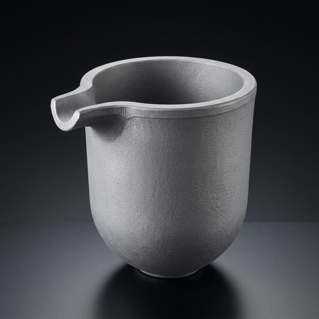
This article combines published research with an engineering RFQ framework. It does not report first-party furnace trials, establish a universal defect threshold, or certify a supplier's machining capability. Flatness, coating thickness, elemental limits, and reuse criteria require agreement against the actual drawing and qualification results. The cover image is a catalogue illustration of a graphite crucible, not evidence of a qualified seed holder assembly.
For adjacent specifications, see 8-inch SiC crucible procurement, vacuum pre-baking and outgassing protocols, managing silicon vapor leakage, preventing graphite crucible thread seizure, porous graphite deflector plates, and TaC coating vs. uncoated graphite crucibles.
Executive Summary: Key Engineering Takeaways
- Separate retention from backside protection. A ring holds the seed; it does not automatically seal a vapor path. A coating changes exposed surface chemistry; it does not hold a seed against gravity or guarantee uniform contact.
- Calculate differential expansion with grade-specific data. Graphite CTE varies with grade, direction, and temperature. The sign of the graphite–SiC expansion difference must be established rather than assumed.
- Measure the assembled interface. Seat flatness, seed bow, coating buildup, ring alignment, and preload can all change the heat transfer path. Low roughness alone cannot establish thermal contact conductance.
- Qualify changes at the intended diameter. A larger seed increases the distance over which expansion mismatch acts. That observation does not establish a universal stress multiplier or prove that adhesive mounting is unsuitable for every 200 mm process.
- Purchase evidence alongside parts. Request dimensional maps, material traceability, coating inspection records, and trial acceptance criteria. Avoid fixed lifetime promises without representative cycling data.
Seed-Lid Interface Architecture
Figure 1. A candidate interface stack. The barrier may be a qualified coating or interlayer; the drawing does not imply that TaC and metallic foil have identical chemistry. Retainers need their own load path and expansion allowance. Gap and layer thicknesses are exaggerated for clarity.
The Physics of Backside Sublimation and Void Formation
PVT growth transports silicon-bearing vapor from a hotter source toward a cooler seed. The seed's rear face can still lose material if the adjacent gap is undersaturated with respect to SiC at the local temperature. Backside loss therefore depends on temperature, vapor composition, transport paths, and the condition of the rear surface. A cooler lid alone does not determine the rate.
Unbonded regions, damaged seed surfaces, porous bond layers, or leakage paths can create locations where rear-face decomposition persists. Local material loss may produce cavities, weaken support, or contribute to defects. A cavity seen after growth is evidence to investigate; it does not identify a unique cause or establish that every cavity becomes a micropipe or basal plane dislocation.
For failure analysis, photograph and map the seed backside, remaining bond or barrier, and mating lid before cleaning. Compare cavity locations with contact marks, ring witness marks, coating damage, and the predicted temperature field. Record whether the defect was already present on the seed. This preserves evidence that scraping or polishing would otherwise remove.
Protection should reduce an identified transport or reaction pathway. A continuous qualified layer may restrict access to graphite, while a revised seat can change local temperature and gap geometry. Neither action substitutes for checking edge leakage. Replacing a cracked coating without investigating the coating edge, preload, and temperature cycle can reproduce the same failure.
Metallic getters require particular caution. Consuming silicon vapor can lower its partial pressure and increase the driving force for further SiC decomposition. A foil can also react, bond, embrittle, or introduce contamination. Do not specify tantalum or niobium foil as an automatic sublimation cure; qualify its chemistry and post-run behavior in the actual assembly.
Thermo-Mechanical CTE Mismatch and Shear Stress Dynamics
Use linear thermal expansion data for the relevant graphite direction and the SiC in-plane direction. A volumetric expansion coefficient cannot be inserted directly into a diameter calculation. For temperature-dependent properties, integrate each material's linear CTE over its own temperature history; seed and holder temperatures need not be identical.
For a simple uniform-temperature screening model, the free radial displacement mismatch is:
Δu(r) ≈ (ᾱholder − ᾱseed) × ΔT × r
Here r is radius, ΔT is the temperature rise, and each average CTE has units of inverse kelvin. The expression returns displacement, not stress. Converting it to interface stress requires a mechanical model with bond thickness, stiffness, slip, friction, geometry, and boundary conditions. Carbonization history and high-temperature relaxation can also change the stress-free reference state.
Increasing radius from 75 mm to 100 mm increases this free displacement by one third when all other inputs are identical. It does not prove a particular increase in peak stress, defect density, or failure probability. A fully bonded interface and a sliding mechanical seat distribute loads differently, so compare complete assemblies rather than assigning a universal diameter penalty.
Thermal-Expansion Clearance Calculation
Consider a deliberately hypothetical 200.00 mm seed inside a 200.50 mm recess, both measured at 20°C. Assume a common rise to 2,200°C, giving ΔT = 2,180 K, and constant average linear CTE values of 4.50 × 10⁻⁶/K for the seed and 5.15 × 10⁻⁶/K for the holder. These values demonstrate the arithmetic and are not recommended material properties.
- Expanded seed diameter:
200.00 × (1 + 4.50 × 10⁻⁶ × 2,180) = 201.962 mm. - Expanded recess diameter:
200.50 × (1 + 5.15 × 10⁻⁶ × 2,180) = 202.751 mm. - Hot diametral clearance:
202.751 − 201.962 ≈ 0.789 mm, corresponding to about0.395 mmradial clearance for concentric parts, calculated before rounding.
Under these reversible, uniform-temperature assumptions, cooling returns the clearance to the original 0.500 mm on diameter. Faster contraction of the holder does not by itself create interference when the original clearance is positive. This example cannot establish a universal minimum gap.
Actual binding can arise from unequal temperatures, deposits, coating buildup, seed or boule growth near a retainer, taper, distortion, or a changed contact reference. Evaluate minimum and maximum material conditions throughout the cycle. Include seed OD tolerance, recess tolerance, concentricity, seed bow, coating thickness on both sidewalls, and any expected deposit allowance. Check the retaining opening separately from the recess: excessive clearance can also reduce capture or create an unacceptable vapor path.
Thermal Contact Conductance and Growth Front Curvature
An effective interface model relates heat flux to the temperature difference between the seed rear face and lid:
q″ = hc × (Tseed,back − Tlid)
Heat flux q″ is in W/m² and effective conductance hc is in W/(m²·K). A practical model can include solid contact, gas-gap conduction, and radiation. Their relative contributions depend on temperature, pressure, gap geometry, contact pressure, gas composition, and surface condition. At reduced pressure, a bulk gas-conductivity value alone may not represent a small gap accurately.
For an illustrative imposed heat flux of 10,000 W/m², an assumed hc = 1,000 W/(m²·K) gives a 10 K interface temperature drop. Halving the assumed conductance doubles that drop to 20 K. This is a sensitivity example, not a measured SiC interface value; in a coupled furnace model the heat flux itself may change.
A radial change in the interface can alter seed temperatures and the growth interface. However, coil geometry, insulation, radiation, and the source-to-seed arrangement also affect curvature. A concave front is therefore not proof of a dished lid. Model competing causes and compare them with dimensional and post-run evidence.
Zhang et al.'s 8-inch thermal-field study reports a simulated radial seed-surface temperature difference changing from 93 K to 11 K with its cavity design. The reported deposition verification was seedless and produced polycrystalline material. It supports examining thermal-field geometry, not transferring those results into a guaranteed single-crystal yield or seed-seat tolerance.
Architectural Comparison of Seed Mounting and Protection
There are two separate design choices: how the seed is retained, and how the backside environment is controlled. An adhesive bond or mechanical retainer addresses mounting. A coating or foil changes an interface and still needs a qualified retention method. The comparison below identifies what each choice requires rather than ranking untested combinations as industry standards.
| Decision criterion | Carbonized adhesive bond | Mechanical retaining ring | TaC-coated backing with separate retention | Metallic foil with separate retention |
|---|---|---|---|---|
| Retention mechanism | Bond transfers load to lid | Edge or shoulder captures seed | Coating does not retain seed | Foil does not retain seed |
| Backside protection question | Is coverage continuous after carbonization? | Where can vapor enter the rear gap? | Are coverage and edges intact? | What reactions occur at both foil faces? |
| Expansion concern | Bond stiffness and reference temperature | Clearance, friction, and local contact load | Coating expansion and retained seed freedom | Reaction bonding, wrinkling, and slip |
| Thermal contact uncertainty | Voids and layer thickness | Preload and seat geometry | Post-coating surface form and contact | Thickness variation and reaction products |
| Preparation evidence | Cure, carbonization, and outgassing records | Cleaning, fit, and assembly sequence | Cleanliness and coating inspection | Handling, cleanliness, and chemistry review |
| Incoming inspection | Coverage and bond-process controls | Seat dimensions and retainer alignment | Thickness map and representative coupons | Foil thickness, defects, and material analysis |
| Scaling question | Does the qualified bond remain uniform at larger diameter? | Is capture maintained over the complete cycle? | Is large-area coverage reproducible? | Are placement and reaction uniform? |
| Reuse decision | Inspect damage after bond removal | Inspect wear, cracks, and fit | Inspect exposed graphite and delamination | Inspect supporting parts after foil removal |
Lee et al.'s TaC-coated crucible study compared coated and conventional crucibles and reported differences in crystal quality and nitrogen incorporation under its test conditions. It concerns the crucible environment; it does not establish zero backside sublimation, a universal coating thickness, or a fixed seed-holder lifetime. Transfer to a particular lid requires assembly-level trials.
Machining and Material Specifications for an RFQ
The following eight-row table is a drawing and evidence checklist. Numerical acceptance values should be filled by the buyer and supplier after reviewing thermal sensitivity, manufacturability, and inspection uncertainty. A finer tolerance is useful only if it controls a relevant failure mechanism and can be measured reproducibly.
| RFQ parameter | What to specify | Inspection evidence | Engineering reason |
|---|---|---|---|
| Seed-seat flatness | Evaluated surface, free or fixtured condition, and limit | Surface map with support method and uncertainty | Controls seat form; flatness is distinct from TTV |
| Seed and lid TTV | Separate thickness limits and measurement locations | Thickness maps of the relevant part | Describes thickness variation, not a substitute for seat flatness |
| Surface roughness | Ra or Rz, cutoff/filter, trace direction, and limit | Profilometer traces using the agreed method | Describes texture without proving thermal conductance |
| Diametral clearance | Minimum and maximum at the reference temperature | Seed OD, recess ID, coating allowance, and tolerance stack | Screens binding, retention, and vapor-path risks |
| Retainer geometry | Capture overlap, bevel, runout, and assembly load | CMM or optical measurements and fit record | Avoids edge point loading and loss of capture |
| Graphite grade and density | Grade, orientation, lot, density method, and thermal-property data | Traceable certificate and agreed density measurement | Supports the model; density alone does not establish CTE |
| Purity and contamination | Element-specific limits, sampling location, and detection limits | GDMS or agreed elemental analysis plus separate ash result | Total ash and individual dopant concentrations are different measures |
| Coating condition | Coated and masked areas, final dimensions, thickness range, and defect criteria | Thickness map, microscopy, and representative witness coupons | Confirms geometry and coverage without claiming absolute absence of pores |
ASTM C838-16(2023) describes bulk density determined from mass and dimensions of as-manufactured graphite at room temperature. It is not an Archimedes liquid-displacement method and does not certify purity or thermal properties. Agree whether its scope and accuracy suit the supplied component before naming it in a purchase specification.
For coating acceptance, distinguish substrate measurements from final coated dimensions. A conformal layer changes a recess diameter at both sidewalls; uneven deposition may alter flatness or capture geometry. Destructive sectioning of a witness coupon can support thickness verification, but the supplier must explain how the coupon represents difficult regions on the actual part.
Procurement Matrix: Match the Assembly to the Uncertainty
Select the next engineering action from the observed problem. Do not change multiple interface variables simultaneously unless the experiment is designed to separate their effects. The table offers trial planning, not a recipe approval or a claim about commercial adoption.
| Situation | Initial evidence to collect | Candidate action | Release condition |
|---|---|---|---|
| Existing bonded seed with rear cavities | Coverage map and carbonization history | Investigate bond continuity and transport paths | Reduced backside loss against a defined baseline |
| Edge cracks after cooling | Crack origin, contact marks, and dimensional stack | Review constraint, clearance, and temperature lag | Capture and clearance acceptable throughout the cycle |
| Coating flakes near the seat | Flake origin and pre-run inspection images | Review edge design, coating process, and handling | Agreed coating integrity after representative cycling |
| Larger seed diameter | Seed bow and contact sensitivity at intended size | Repeat fit and thermal-model sensitivity checks | Intended-diameter trial meets acceptance criteria |
| Suspected contamination | Elemental analysis and handling traceability | Isolate grade, coating, foil, and cleaning contributions | Contamination remains within the process budget |
| Uncertain lid reuse | Dimensional drift and post-run damage history | Set inspection-based retirement criteria | Each reused part remains within approved limits |
When sending an RFQ, include a baseline drawing revision and identify the single change under evaluation. Ask suppliers to separate lid, retainer, coating, inspection, cleaning, and rework costs. Discuss the drawing and qualification scope before converting a proposed tolerance into a production purchase requirement.
Seed Holder and Crucible Lid Commissioning Checklist
- Define the process envelope: record seed size, thickness, bow, orientation, pressure, temperatures, mounting direction, growth duration, and cooling schedule.
- Confirm material traceability: obtain graphite grade, lot identity, directional thermal data, and an elemental analysis method with detection limits.
- Inspect final geometry: measure seat flatness, relevant TTV, texture, concentricity, coating buildup, and capture dimensions under the agreed support condition.
- Check the full tolerance stack: evaluate both minimum clearance and maximum allowed freedom over the cycle, including thermal lag and deposits.
- Separate purity measures: specify element-specific contamination limits independently of total ash; retain sampling and test records.
- Agree cleaning and conditioning: use a qualified process compatible with the graphite, coating, and any interlayer. Do not adopt a generic bake temperature or vacuum level as a release criterion.
- Perform a controlled dry fit: use an appropriate dummy seed and documented assembly procedure; inspect contact marks without damaging the functional surfaces.
- Set trial acceptance before growth: define backside loss, cracks, retention, coating condition, and relevant crystal-quality measurements against a baseline.
- Preserve post-run evidence: map damage before cleaning, record dimensional drift, and quarantine parts exceeding the approved limits.
- Authorize reuse by inspection: apply the agreed retirement criteria rather than an assumed number of cycles.
Frequently Asked Questions
Why can backside sublimation occur with a tightly clamped seed?
Clamping does not guarantee continuous contact or a sealed vapor environment. Surface form, seed bow, roughness, and local load can leave gaps. Those regions can support material loss if local temperature and vapor composition favor decomposition. Increase preload only after checking edge stress, capture, and the thermal effect; more force is not automatically a cure.
Can carbonized adhesive still be considered for a 200 mm seed?
Diameter alone does not disqualify it. Qualification must establish coverage, carbonization behavior, contamination, thermal contact, and mechanical response over the intended cycle. Compare a changed adhesive process with the existing baseline. The sources cited here do not establish a universal commercial preference or prove that all 200 mm adhesive mounts fail.
Does a TaC coating eliminate backside sublimation?
No universal elimination claim follows from a coated-crucible study. Coating integrity, exposed edges, interface gaps, thermal conditions, and retention still matter. A coating may change chemical interaction with graphite, but its benefit at the seed backside needs direct evaluation. Specify measurable coating acceptance and trial outcomes rather than an unconditional protection guarantee.
How does seed thickness affect bowing and temperature?
For a plate with unchanged material and boundary conditions, bending rigidity scales approximately with thickness cubed. Through-thickness thermal resistance scales with thickness divided by conductivity. A thicker seed can therefore resist bending while changing the temperature distribution. Which surface becomes hotter depends on the imposed thermal boundaries; thickness alone does not establish backside temperature or a sublimation rate.
Can tantalum or niobium foil be treated as a compliant getter?
A foil may change contact and chemistry, but compliance before heating does not prove continued slip after reaction. Silicon consumption can promote further decomposition, while reaction products may bond or distort the interface. Require contamination review, retention analysis, and post-run examination before adopting a foil. Metallic foil and an already formed TaC coating are different design choices.
Does a concave growth front prove the seed seat is poorly machined?
No. A nonuniform seat can contribute, but coil position, insulation, radiation, source geometry, and changing boule shape also influence the thermal field. Compare the measured seat map with model sensitivity and run evidence. A single curvature observation cannot isolate the contact conductance or justify a universal micrometre flatness limit.
How many growth cycles should a lid survive?
There is no transferable count established here. Retirement depends on cracks, dimensional drift, exposed graphite, coating loss, contamination, and the qualified cleaning process. Build a reuse history for the actual part and recipe. Procurement should compare cost per accepted run using observed performance, including inspection and rework, rather than assuming a fixed lifetime from the coating name.
Sources and References
- Zhang et al., Materials (2023): Design and Optimization of Thermal Field for PVT Method 8-Inch SiC Crystal Growth. Supports thermal-field sensitivity and cavity-design discussion; the deposition verification was seedless and polycrystalline. It does not supply universal seed-holder machining limits.
- Lee et al., Materials Science Forum (2014), pp. 26–30: Effect of TaC-Coated Crucible on SiC Single Crystal Growth. Reports a coated-versus-conventional crucible comparison. Its reported conditions and outcomes cannot establish every coated lid's backside protection or service life.
- ASTM International: C838-16(2023): Standard Test Method for Bulk Density of As-Manufactured Carbon and Graphite Shapes. Defines a mass-and-dimensions density method. Obtain the standard and agree applicability before using it for acceptance.
The clearance arithmetic and RFQ matrices are engineering screening tools developed for this guide. They are separate from the cited experimental results. Reassess the assembly when changing seed diameter, graphite grade, coating, mounting method, or temperature cycle.
Request an Engineering Review for Seed Holder and Lid Assemblies
For seed detachment, rear-face cavities, edge cracks, or inconsistent thermal contact, send the lid and retainer drawings together with seed dimensions, graphite grade, coating details, furnace temperature cycle, and photographs of the current failure. Identify which requirements are already qualified and which remain proposals.
Ask for a drawing-specific manufacturability review, an inspection plan, and a sample qualification scope. Confirm achievable tolerances, coating coverage, elemental reporting, quantities, and delivery requirements before ordering. Production yield, coating lifetime, and thermal contact conductance require process evidence beyond a part quotation.
Contact our engineering team to review your crucible lid drawings and RFQ specifications.
Author

Categories
More Posts
Vacuum Pre-Baking and Outgassing Protocols for SiC PVT Graphite Crucibles
Qualify vacuum pre-baking for SiC PVT graphite crucibles with RGA checks, supplier evidence, handling limits, and a practical engineering procurement checklist.
Rigid vs. Soft Graphite Felt in SiC PVT Hot Zones: Precursor Chemistry, Thermal Drift, and 200mm Scaling
Compare rigid vs. soft graphite felt insulation for SiC PVT hot zones. Review precursor chemistry, thermal drift, and 200mm RFQ checks before requesting a quote.
Porous Graphite Deflector and Filter Plates in SiC PVT: Porosity, TaC Passivation, and Stoichiometric Flow Control
Select porous graphite deflector and filter plates for SiC PVT: compare porosity, verify TaC coverage, and prepare permeability and purity data for an RFQ.