
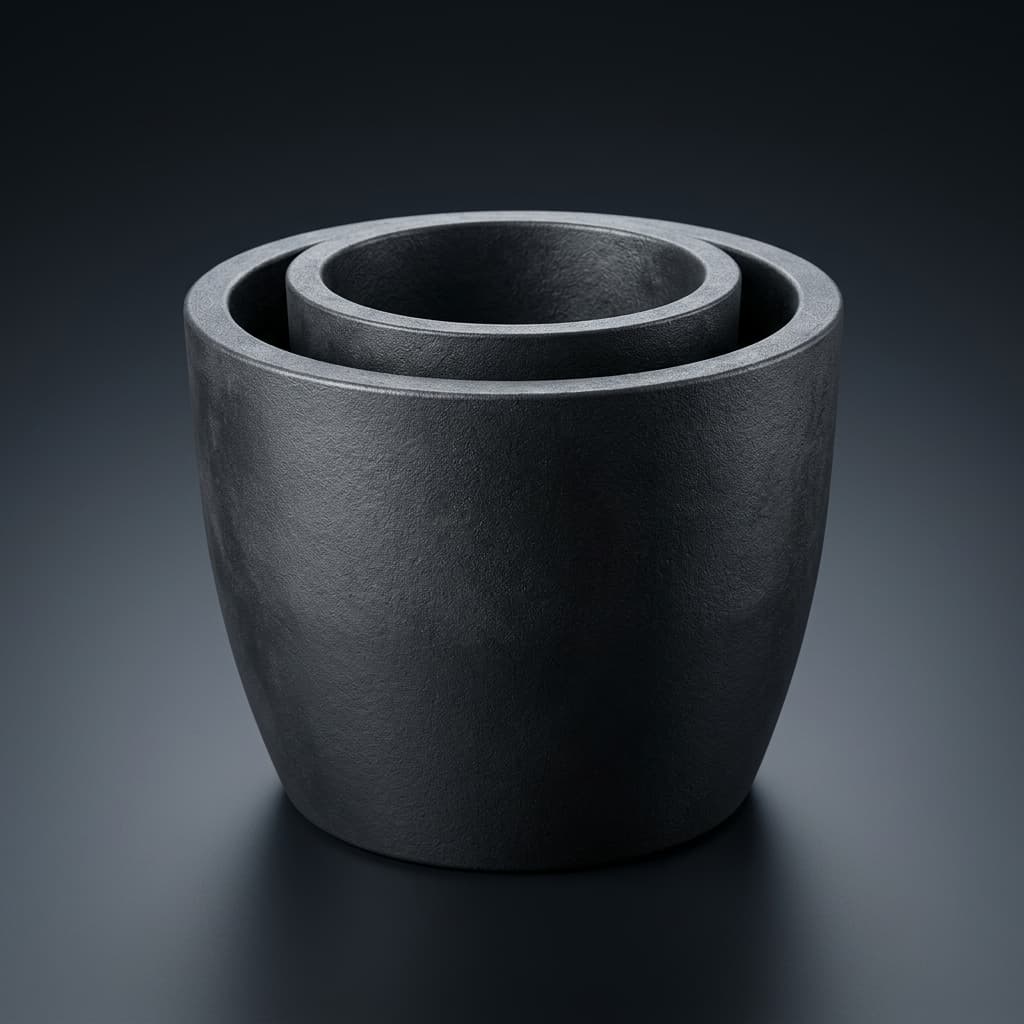
Vacuum Pre-Baking and Outgassing Protocols for SiC PVT Graphite Crucibles
Qualify vacuum pre-baking for SiC PVT graphite crucibles with RGA checks, supplier evidence, handling limits, and a practical engineering procurement checklist.
Vacuum pre-baking for SiC PVT graphite crucibles should be qualified against a measured furnace background, the actual graphite grade, and the supplier's temperature limits. A low total pressure or a supplier's “pre-baked” label alone does not establish that a crucible is ready for crystal growth. Release the assembly only after its gas trends, handling history, and agreed acceptance criteria have been reviewed together.
This guide helps process engineers and procurement teams specify an empty-assembly conditioning run, interpret Residual Gas Analysis (RGA), and compare factory pre-baking with in-house processing. It provides a qualification workflow and worked calculations; it does not report a measured production trial or establish a universal furnace recipe.
Scope, Assumptions, and Engineering Limits
Published and reviewed on November 3, 2026. The scope is high-purity isostatic graphite crucibles, lids, and adjacent hot-zone parts for 150mm and 200mm Physical Vapor Transport (PVT) SiC growth, including bare graphite and CVD tantalum carbide (TaC)-coated assemblies. The audience is global; costs, equipment limits, and acceptance specifications must be set locally.
High-vacuum conditioning and reduced-pressure argon growth are different operating states. An instrument's vacuum requirement is not automatically the growth chamber's pressure specification. Obtain approved temperature, pressure, ramp, cooling, and gas limits from the furnace and component suppliers before defining a run. A temperature measured by a pyrometer also needs a documented sight line and emissivity method.
For adjacent specifications, see 8-inch SiC crucible procurement, evaluating crucible porosity and density, halogen purification and GDMS purity, and TaC coating vs. uncoated graphite crucibles. Those topics complement the gas-release assessment; purity certification and outgassing qualification answer different questions.
Executive Summary: Key Engineering Takeaways
- Specify evidence, not just a bake temperature. Request the actual part loading, temperature trace, gas conditions, pressure history, and post-bake handling record.
- Compare like with like. Record an empty-furnace background and a loaded run at comparable temperature, pumping configuration, and RGA settings.
- Treat mass 28 as ambiguous. CO and nitrogen overlap on a conventional unit-resolution quadrupole. Interpret multiple peaks rather than assigning all of mass 28 to one gas.
- Do not transfer a recipe by wafer diameter alone. Wall thickness, coating coverage, graphite grade, furnace conductance, and load mass can change the required conditioning.
- Qualify the packaging route. Factory pre-baking is useful only if transport, storage, unpacking, and incoming checks preserve the agreed condition.
Graphite Microstructure: Porosity, Bulk Density, and Gas Trapping Mechanics
Synthetic graphite contains pores and surfaces that can retain gases or contamination introduced during machining, handling, cleaning, and storage. The resulting gas load is specific to the material and its history. A bulk-density value does not determine the open pore size distribution, accessible surface area, moisture uptake, or required bake duration.
For example, using an assumed bulk density of 1.84 g/cm³ and a skeletal density of 2.26 g/cm³ gives an estimated total void fraction of 1 − 1.84 / 2.26 ≈ 18.6%. This is a density-based illustration, not a measurement of open porosity. Ask for the grade's test method before comparing a supplier's porosity claim with another grade.
Moisture adsorption and capillary condensation
Moisture behavior depends on pore geometry, surface chemistry, humidity, temperature, and exposure time. It is not valid to infer a fixed moisture percentage after 48 hours from crucible diameter alone.
A useful consistency check is the Kelvin relation. With liquid-water assumptions at 25°C, complete wetting, surface tension 0.072 N/m, and molar volume 18 × 10⁻⁶ m³/mol, r = −2γVm / (RT ln(RH)) gives a meniscus radius of about 1.1–1.3 nm at 40–45% RH. This idealized estimate does not support a blanket claim that micron-wide graphite pores fill with liquid water at ordinary cleanroom humidity. Real graphite can still adsorb moisture, but its uptake needs measurement.
What heating can and cannot establish
Heating and evacuation can reduce removable gas loads. Surface desorption, chemical decomposition, pore transport, and chamber-wall outgassing may contribute at the same time. A warm drying step is not equivalent to a qualified high-temperature conditioning cycle; neither step proves trace-metal purity. Use lot-specific material analysis for elemental contamination and a separate gas-release assessment for conditioning.
Vapor Phase Stoichiometry and Seed Defect Dynamics
Water- and oxygen-bearing contamination can react with hot carbon and disturb the intended growth environment. Two relevant carbon reactions are C + H₂O ⇌ CO + H₂ and C + CO₂ ⇌ 2CO. The first is the water-gas reaction; the water-gas shift reaction is CO + H₂O ⇌ CO₂ + H₂. Actual reaction extent depends on temperature, pressure, composition, and transport.
These mechanisms justify controlling contamination. They do not establish that a particular RGA peak causes a specified micropipe density, polytype transition, or resistivity failure. Seed condition, thermal gradients, source material, intentional doping, leaks, and insulation history also require investigation.
The study Design and Optimization of Thermal Field for PVT Method 8-Inch SiC Crystal Growth examines the thermal-field design of an 8-inch PVT system. It supports treating furnace geometry and heating conditions as process-specific; it does not validate the bake-out stages or RGA release limits proposed here.
Mathematical Modeling: Diffusion Kinetics and Wall Thickness Scaling
If diffusion is the controlling mechanism, a characteristic time can scale as t ∝ L² / D_eff, with diffusion length L and effective diffusivity D_eff. Surface desorption, gas transport through pores, and solid-state diffusion have different rate controls, so a single fitted diffusivity must not be transferred without checking the mechanism.
As an illustrative comparison, changing the effective path from 18mm to 32mm gives (32 / 18)² ≈ 3.16. That ratio applies only when diffusivity, boundary conditions, geometry assumptions, and the controlling mechanism remain comparable. The effective path also depends on whether gas can escape through one or both faces.
This calculation is a reason to requalify thicker parts, not a rule that all 200mm crucibles need three times the dwell, or a fixed 40–60% extension. Set the actual hold using gas trends from the proposed assembly and loading configuration.
Vacuum Pumping Architecture and Furnace Sizing Requirements
Select the complete vacuum train
Evaluate the high-vacuum pump, backing pump, valves, line conductance, traps, exhaust treatment, and material compatibility together. A turbomolecular pump does not eliminate contamination from other components; an oil diffusion system needs an assessment of backstreaming controls. Neither pump type establishes crucible cleanliness by itself.
If moisture, particulates, or purification residues are expected, review the gas load and service procedure with the pump supplier. Do not assume that every graphite lot releases acid gases, or prescribe a chemical trap without checking compatibility and exhaust requirements.
Calculate effective speed from a measured gas load
Under a quasi-steady approximation, gas throughput, chamber pressure, and effective pumping speed are related by Q = P × S_eff. Conductance can make the chamber's effective speed much lower than a pump's catalogue rating. Base pressure of an empty system and pressure during active outgassing are different quantities.
Worked example, using assumed inputs: if Q = 1.5 mbar·L/s and the desired operating pressure is 1 × 10⁻⁴ mbar, then S_eff = 15,000 L/s. If the chamber delivers only 1,000 L/s, the corresponding steady pressure is approximately 1.5 × 10⁻³ mbar, neglecting other loads. These numbers are arithmetic examples, not measured graphite emissions or a pump purchase specification.
Use a measured pressure/temperature history to decide whether to change the load size, pumping conductance, or heating program. No universal ramp rate follows from this example.
Thermal Profile: A Four-Stage Qualification Workflow
The stages below organize a qualification discussion. They are not an executable temperature/time recipe. The furnace OEM and graphite or coating supplier must approve setpoints and transitions for the actual assembly. Stages can overlap, and a high-temperature soak does not guarantee that a part will remain gas-free at a higher growth temperature.
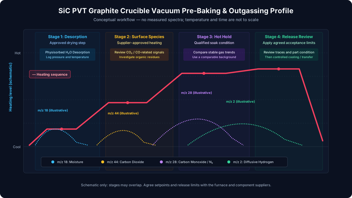
Figure: conceptual sequence and gas channels to investigate. The curves are illustrative, not measured desorption spectra or a scaled time/temperature program.
Stage 1: Moisture desorption
Start with the supplier-approved drying and evacuation step. Log pressure and temperature together, and monitor the water-related signal when the RGA sampling system is within its operating limits. A falling water signal is useful trend information; a percentage decrease from its peak alone is not a release criterion.
Stage 2: Surface species and residual contamination
Progress through the approved heating program while tracking carbon oxides and hydrocarbon-related signals. If pressure or a monitored channel departs from the qualified envelope, follow the furnace's hold or abort procedure. Persistent hydrocarbon signals warrant a cleaning-history review rather than an automatic increase in temperature.
Stage 3: Higher-temperature conditioning
Assess whether the loaded assembly approaches a repeatable background at the approved soak condition. Record the location and method of temperature measurement. Use argon purge cycles only if that sequence is approved for the furnace and part; purging and deep evacuation are not interchangeable evidence of cleanliness.
Stage 4: Final hold and release review
Review the stable gas trends, temperature history, and component inspection against the agreed release specification. A final soak is not a substitute for the supplier's purification process, nor proof of complete nitrogen removal. Keep source powder and seeds out of the initial empty-assembly qualification unless a separate combined process has been validated.
Controlled cooling and transfer
Cool and vent using the approved inert-gas procedure, with gas quality, part-temperature limits, and exposure time recorded. An argon backfill of 500–800 mbar remains below ordinary atmospheric pressure; it is not a positive-pressure barrier against room-air leaks. Protect the cooled parts during transfer and preserve package-to-run traceability.
Technical Comparison: Conditioning Stages and Release Evidence
| Step | Purpose | Record | Transition or acceptance basis |
|---|---|---|---|
| Incoming inspection | Establish material and handling history | Lot, grade, coating, package condition, dimensions | Agreed drawing and incoming specification |
| Stage 1: Drying | Reduce removable moisture | Temperature, pressure, water-related signal | Qualified drying envelope and gas trend |
| Stage 2: Surface conditioning | Investigate carbon oxides and organic residues | Multi-mass spectrum and pressure history | Approved envelope; investigate unexplained peaks |
| Stage 3: Higher-temperature hold | Assess slower gas release | Part loading, measurement location, stable-temperature trend | Repeatability against a comparable background |
| Stage 4: Final assessment | Decide whether the assembly can be released | Calibration status, gas trends, signed run review | Lot- and furnace-specific release limits |
| Controlled cooling | Preserve part integrity and condition | Cooling trace, gas quality, vent temperature | Furnace and coating supplier limits |
| Packaging and transfer | Limit recontamination | Seal check, storage history, exposure time | Validated packaging and incoming acceptance plan |
Residual Gas Analysis (RGA) Gating Baselines
A total-pressure gauge cannot identify the gas mixture. RGA adds composition information, but its signals require calibration and interpretation. The Stanford Research Systems RGA operating manual, sections 2-8 through 2-12 explains fragmentation, overlapping peaks, and sensitivity factors. Those factors depend on gas species and instrument settings; a raw ion-current threshold cannot be transferred between instruments as a universal partial-pressure limit.
Proposed qualification method: take an empty-furnace reference, then a loaded-assembly trace with comparable thermal and pumping conditions. Define the stable evaluation interval, instrument settings, background treatment, and allowable deviations before judging the run. Where the chamber is at argon pressures above the analyzer's limit, use an approved pressure-reduction sampling system or isolate the analyzer. A sampled pressure needs a characterized transfer relation before it can represent chamber partial pressure.
The following channels are diagnostic prompts, not a table of certified “growth-ready” thresholds. Set numerical limits using validated process runs, calibration uncertainty, and the intended substrate specification.
| Channel (m/z) | Candidate contribution | Interpretation limit | Qualification action |
|---|---|---|---|
| 2 | Hydrogen | Can include chamber and instrument background | Compare the loaded and background trends |
| 18 | Water | Chamber surfaces and the sample can both contribute | Check drying and handling history |
| 28 | CO and/or nitrogen | A single peak cannot identify either concentration | Review multiple fragments and reference spectra |
| 32 | Oxygen | A possible air-ingress signal, not a leak diagnosis alone | Compare air-related channels and perform an approved leak test |
| 44 | Carbon dioxide | Fragmentation also contributes to other masses | Include its contribution in mixture interpretation |
| 15 / 16 | Hydrocarbon-related fragments and other species | Mass 16 is not specific to methane | Review the wider spectrum and cleaning history |
Distinguishing carbon monoxide from nitrogen at mass 28
Use reference fragmentation patterns and calibrated response factors across several masses rather than a fixed 14/28 or 12/28 cutoff. CO₂ and hydrocarbons can add overlapping fragments, making a two-gas interpretation incomplete. The NIST Chemistry WebBook carbon monoxide entry provides an electron-ionization reference spectrum; it does not replace calibration of the installed RGA.
When quantitative separation is uncertain, retain the combined mass-28 trend and document that uncertainty. Do not relabel it “nitrogen removed” or report exact CO/N₂ fractions from two uncalibrated peaks.
Engineering Decision Matrix: In-House vs. Offline vs. Factory Pre-Baking
Choose the route from measured capacity, accepted-lot yield, and the evidence needed at receipt. There is no universal best choice based solely on the number of PVT reactors.
| Decision metric | Production PVT reactor | Dedicated offline furnace | Supplier factory pre-baking |
|---|---|---|---|
| Equipment investment | Uses available production equipment; may need instrumentation | Requires equipment, utilities, and qualification | Service and qualification costs belong in the quote |
| Production capacity | Occupies time that may otherwise support growth | Moves the conditioning load off production equipment | Can reduce in-house conditioning if incoming checks pass |
| Contamination control | Requires chamber and insulation background assessment | Separates initial gas loads; still needs maintenance | Depends on supplier handling, transport, and acceptance |
| Verification access | Uses the site's available sensors and sampling setup | Can be configured for repeatable batch comparison | Requires usable run records, not only a certificate label |
| Flexibility | Competes with production scheduling | Depends on batch utilization and changeover | Depends on lead time, lot size, and supplier capacity |
| Release responsibility | Site reviews the actual assembly run | Site qualifies transfer from the offline furnace | Supplier evidence and site incoming checks must agree |
Illustrative cost comparison: assume an empty conditioning cycle occupies 30 reactor-hours, the site's assigned occupancy cost is $40/hour, incremental labor and utilities are $180, and a supplier quotes a $250 pre-bake premium plus $100 incoming verification. The comparison is 30 × $40 + $180 − $250 − $100 = $1,030 per accepted assembly before freight, rework, and qualification costs. These are assumed inputs, not market prices, supplier commitments, or measured savings. Exclude overhead already included in the hourly rate to avoid double counting; released capacity has value only if it can be used.
Ask suppliers to quote conditioning, packaging, verification, and rework separately. Compare cost per accepted assembly rather than the advertised bake surcharge.
TaC-Coated Crucibles: Outgassing Differences and Thermal Stress Limits
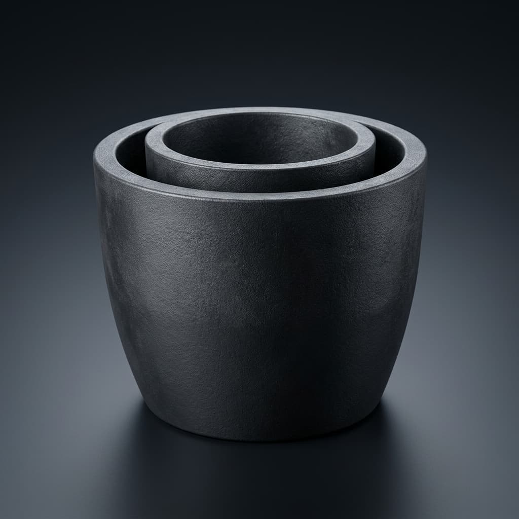
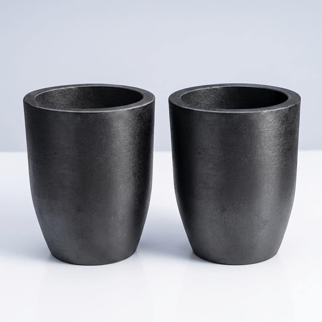
A graphite product image illustrates the component geometry; it is not evidence of coating coverage or a completed bake-out.
A coating can change gas access to the substrate, but coverage, uncoated faces, defects, and processing history matter. Do not assume an 80–90% moisture reduction or complete pore sealing without measurements on the supplied coating system.
Request substrate preparation records, coating coverage and thickness specifications, thermal-cycle limits, and an inspection method for cracking or blistering. Expansion mismatch and thermal gradients are reasons to qualify a ramp; they do not establish a universal 3°C/min ceiling for every TaC-coated part. Follow the coating supplier's approved heat-up and cool-down envelope.
Consumables Interaction: Hot-Zone Insulation Outgassing
The measured chamber signal includes insulation, shields, fixtures, seals, and chamber surfaces as well as the crucible. Record which components were replaced or exposed to air. Otherwise, a “crucible outgassing” comparison may actually compare different hot-zone histories.
Where practical, compare the empty furnace, the furnace with its intended insulation package, and the added crucible assembly. Keep the heating program and instrument settings comparable. This staged comparison helps locate a gas load; automatically doubling dwell times for fresh felt does not establish its removal.
Cleanroom Handling, Barrier Packaging, and Storage
Specify the maximum validated storage interval, opening conditions, dry-gas requirements, and cumulative ambient exposure. There is no universal four-hour re-bake trigger: graphite grade, humidity, cleaning history, and package integrity all influence recontamination.
For supplier pre-baked parts, agree on low-shedding contact materials, barrier performance, seal verification, and a transfer method that avoids direct contact with loose desiccant. A humidity indicator is an environmental indicator, not a measurement of the graphite's moisture content. Read it using its own instructions; color conventions vary.
After a breached seal or unknown exposure, quarantine the assembly and apply the site's approved reassessment or reconditioning procedure. Do not equate cleanroom particle classification with a controlled moisture or chemical-contamination history.
Failure Modes, Diagnostics, and Corrective Actions
| Observation | Possible contributors | Evidence to collect | Next action |
|---|---|---|---|
| Persistent water-related signal | Damp surfaces, handling, sampling background | Comparable blank trace, exposure record | Locate the load before extending the approved drying step |
| Sustained mass-28 signal | CO, nitrogen, air ingress, overlapping fragments | Multi-mass trends, reference responses, leak-check record | Separate likely contributors; keep uncertainty explicit |
| Hydrocarbon-related peaks | Cleaning residue, pump train, fixtures | Cleaning log, blank run, broader spectrum | Review contamination sources and compatibility |
| Resistivity or polytype variation | Doping, thermal field, source, seed, gas contamination | Growth history and material characterization | Investigate multiple causes; do not diagnose from one RGA mass |
| Coating blisters or cracks | Preparation, adhesion, thermal gradients, trapped gas | Coating inspection and actual thermal trace | Stop reuse pending supplier disposition |
| Optical temperature drift | Viewport deposits, sight line, emissivity changes | Viewport inspection and calibration history | Restore a verified temperature-measurement method |
A rate-of-rise test also needs correct units: dP/dt is a pressure-rise rate (for example, mbar/s), while V × dP/dt is a gas throughput (mbar·L/s). It includes outgassing as well as possible leaks. Define chamber volume, temperature stability, isolation limits, and the approved test method before using it as a release gate.
Procurement and Engineering Commissioning Checklist
- Identify the part revision, graphite grade, coating coverage, lot number, and material-analysis method.
- Record packaging integrity, storage conditions, cleaning history, and ambient exposure.
- Agree an empty-assembly qualification plan and the OEM-approved thermal and pressure envelope.
- Record the full furnace loading, insulation history, temperature-measurement method, and pumping configuration.
- Capture a comparable background and the loaded gas/pressure traces, with RGA calibration and sampling conditions.
- Define channel limits, evaluation interval, measurement uncertainty, and escalation rules before release.
- Inspect dimensional and coating condition as required after the qualification cycle.
- Specify cooling, venting, packaging, transfer, and incoming verification for factory pre-baked parts.
- Keep GDMS or other elemental analysis separate from moisture and outgassing evidence.
- Assign a reviewer and retain the signed release record; define what changes require requalification.
A practical RFQ should ask: “Can you supply this drawing revision with an agreed conditioning record and packaging specification? State your approved temperature envelope, gas/pressure measurement method, acceptance criteria, and incoming recheck requirements.” Leave numerical limits open for engineering agreement rather than copying unsupported defaults.
Frequently Asked Questions
How long can a baked crucible remain exposed in a cleanroom?
There is no grade-independent exposure allowance. Define the limit from controlled storage/exposure comparisons and the site's incoming gas-release criteria. Record humidity and cumulative exposure; use the approved reassessment procedure after an excursion.
Can source powder and a new crucible be baked together?
Use an empty assembly for initial qualification so that the crucible and hot zone can be assessed separately. A combined powder-conditioning cycle needs its own validation because the source contributes gases and can change during heating. Empty qualification does not automatically approve a combined process.
Do 200mm crucibles always need a longer soak than 150mm parts?
No fixed extension follows from diameter alone. The wall-path calculation above illustrates one diffusion-limited case. Compare the actual geometry, grade, coating, loading, and gas trends before changing the program.
Must a TaC-coated crucible receive the same full cycle before every run?
Reuse depends on the qualified maintenance procedure, coating condition, cleaning method, and exposure history. Neither automatic full re-baking nor a universal shortened cycle is justified. Define requalification triggers with the component supplier.
Does factory pre-baking eliminate commissioning cost?
It may reduce in-house furnace occupancy, but incoming verification, transport integrity, and possible reconditioning remain part of the comparison. Use the cost model with local inputs and an accepted-assembly basis. A supplier label alone does not justify direct loading into production.
Can argon flushing replace vacuum conditioning?
It may be part of an approved process, but it is not automatically equivalent. Temperature, flow, pressure, gas purity, and transport determine what is removed. Qualify the proposed method against the same acceptance criteria rather than declaring every argon process ineffective.
Can an ultrasonic solvent bath be used before baking?
Use only the graphite or coating supplier's validated cleaning procedure. Liquid cleaning can introduce absorbed material, residues, particles, or coating damage. A blanket approval or prohibition is inappropriate without the part specification and a demonstrated drying/cleanliness method.
Sources and References
- Stanford Research Systems: RGA100/RGA200/RGA300 Operating Manual and Programming Reference, revision 1.9, September 2026. Sections 2-8 through 2-12 cover spectral interpretation and calibration; Appendix B addresses pressure reduction. This is instrument guidance, not a SiC bake recipe.
- NIST Chemistry WebBook, SRD 69: Carbon monoxide: electron-ionization mass spectrum. Reference data for interpreting candidate fragments, not a transferable release threshold.
- Zhang et al., Materials 16(2), 767 (2023): Design and Optimization of Thermal Field for PVT Method 8-Inch SiC Crystal Growth. Context for equipment-specific thermal-field design; it does not establish crucible outgassing limits.
Source scope reviewed November 3, 2026. The workflow, diagnostic tables, and calculations above are engineering screening aids. They do not claim compliance with an unnamed SEMI specification or a graphite standard, and no factory trial, customer result, or independent certification is asserted.
Request a Pre-Bake Qualification Review
For an engineering discussion, send your crucible drawing, graphite grade, coating specification, furnace limits, planned conditioning location, and required acceptance evidence. Ask for a written scope covering the proposed bake process, packaging, incoming checks, and quote assumptions before selecting a supply route.
Author

Categories
More Posts
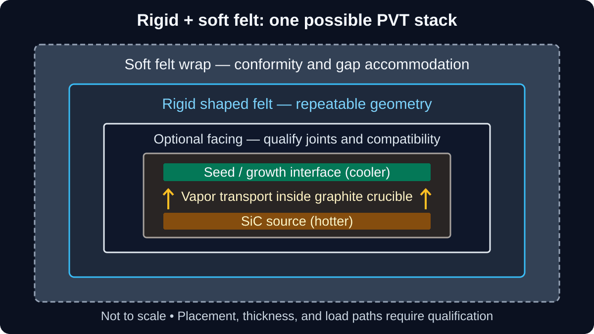
Rigid vs. Soft Graphite Felt in SiC PVT Hot Zones: Precursor Chemistry, Thermal Drift, and 200mm Scaling
Compare rigid vs. soft graphite felt insulation for SiC PVT hot zones. Review precursor chemistry, thermal drift, and 200mm RFQ checks before requesting a quote.
Porous Graphite Deflector and Filter Plates in SiC PVT: Porosity, TaC Passivation, and Stoichiometric Flow Control
Select porous graphite deflector and filter plates for SiC PVT: compare porosity, verify TaC coverage, and prepare permeability and purity data for an RFQ.
Managing Silicon Vapor Leakage in SiC PVT: Sealing Strategies for Graphite Crucibles
Use this RFQ guide to manage silicon vapor leakage in SiC PVT graphite crucibles with density, thread tolerance, labyrinth seal, and TaC coating checks.