

CVD TaC Coating Failure Modes in SiC PVT: Delamination Mechanics, Silicon Vapor Infiltration, and Substrate DFM Standards
Diagnose CVD TaC coating failure in SiC PVT: compare delamination, vapor ingress and graphite DFM risks, then prepare a drawing review and supplier RFQ.
CVD TaC coating failure in SiC PVT should be investigated as a coupled coating, graphite substrate, and furnace problem. Edge flakes suggest a mechanical investigation; blisters or deposits around a defect suggest checking vapor access and interfacial reactions. Appearance alone cannot establish the root cause. Preserve the failed part, compare it with an unused witness coupon, and connect microscopy findings to its actual thermal history before changing the next purchase specification.
For drawing evaluations, compare our TaC coated graphite crucibles, porous graphite with TaC coating, and CVD TaC & SiC coating services, or request an engineering drawing review.
1. Operating Envelope, Process Boundaries, and Failure Definition
Published and reviewed: November 12, 2026. This guide is for crystal growth engineers, hot-zone designers, and semiconductor procurement teams worldwide qualifying coated graphite for SiC physical vapor transport (PVT), including 150 mm and 200 mm programs. It focuses on diagnosis and supplier acceptance criteria. It does not prescribe a furnace recipe, certify a supplier, or predict a guaranteed number of growth runs.
Evidence and limits: The cited literature covers different coating routes and environments. Nakamura and Shigetoh studied sintered TaC on graphite in SiC sublimation growth; Kumar and colleagues studied CVD TaC/SiC under short oxyacetylene exposure; Kim and colleagues studied coated carbon/carbon composites under an arc heater. These are relevant engineering references, but their results cannot be transferred unchanged to CVD-coated graphite in a low-pressure PVT reactor. This article provides an engineering synthesis, a hypothetical stress calculation, and a qualification workflow, rather than reporting new furnace measurements.
For each qualification, record source-zone and lid temperatures, pressure, gas composition, temperature gradients, ramp history, cumulative exposure hours, and assembly configuration. PVT source temperatures can exceed 2,000°C, but the controller setpoint is not necessarily the temperature at the coating interface. The local silicon-bearing vapor environment also differs between the source, wall, lid, and porous flow-control parts. Record measurement locations and uncertainty before comparing two suppliers' results.
Define failure before testing: examples include exposed graphite in a protected zone, detached flakes, loss of assembly fit, or contamination exceeding the customer's limit. Keep cosmetic discoloration separate from confirmed barrier loss. A usable acceptance specification states what is inspected, where, with what resolution, and when the part must be retired.

Product illustration of a TaC-coated graphite assembly; this image is not a failed-part micrograph or service-life test result.
2. Mechanical Failure Mode: CTE Mismatch, Interfacial Stress, and Spallation
Coating and substrate expand differently during deposition, cooling, and reheating. Their coefficients of thermal expansion (CTE), elastic properties, geometry, and interface condition influence the resulting stress. A room-temperature CTE value cannot be applied across the entire cycle without checking its measurement interval and material direction. Isostatic graphite also retains grade-dependent microstructure and porosity.
Distinguish Coating Stress from Interface Shear
A simplified elastic thin-film estimate is:
σ_f ≈ [E_f / (1 − ν_f)] × (α_s − α_f) × (T − T_ref)
Here, E_f and ν_f describe the coating, α_s and α_f are substrate and film linear CTEs, and T_ref is an assumed stress-free reference temperature. This estimates in-plane biaxial film stress for a bonded film on a much thicker substrate with uniform temperature and constant properties. It is not an equation for interfacial shear strength. Deposition stress, creep, cracking, and temperature-dependent properties can change both the magnitude and reference state.
As a hypothetical screening example, assume E_f = 300 GPa, ν_f = 0.24, α_f − α_s = 1.5 × 10⁻⁶/K, and cooling by 1,800 K. The model gives about 1.07 GPa of tensile film stress. These are illustrative inputs, not measured properties of our products or an allowable stress. With a higher film CTE, idealized cooling from the reference state puts the film in tension; compressive buckling requires a compressive stress state. Neither peeling nor its appearance proves the stress sign throughout a real furnace cycle.
At an edge, thread root, or coating termination, load transfer creates localized interface stresses. Diagnosis therefore needs the actual thickness map, local curvature, substrate properties, and thermal gradient. A single universal bond-strength threshold or stress concentration factor cannot approve every crucible drawing.
Thickness and Stored Elastic Energy
At comparable film stress, stored elastic energy per unit area scales approximately as σ_f² × t_f / E_f, where t_f is coating thickness. This explains why added thickness can increase the driving force for cracking or delamination. Actual fracture depends on flaw geometry, interface toughness, and loading; the scaling relation does not establish a universal critical thickness.
The growth study by Nakamura and Shigetoh supports considering graphite CTE when scaling TaC-coated components. Its coating was made by wet powder forming and sintering, so its durability result does not validate a CVD thickness window. Select a candidate thickness with the coater, then qualify coverage and thermal cycling on the intended substrate and geometry.
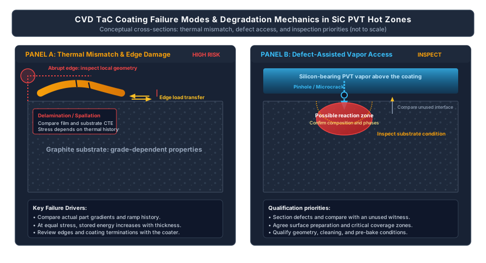
Conceptual cross-sections, not to scale. Panel A shows thermal mismatch and edge load transfer. Panel B shows a possible defect-access pathway requiring cross-sectional and chemical confirmation; it does not establish a reaction temperature or a particular silicide phase.
3. Chemical Failure Mode: Silicon Vapor Infiltration and Interfacial Reactions
Pinhole Access and Subsurface Damage
A connected pore or crack can give silicon-bearing species access to graphite underneath an otherwise protective coating. Reaction products, changes in local pore structure, and loss of interfacial support can then contribute to lifting or blistering. Silicon reacting with carbon can form SiC, but the resulting local displacement depends on the consumed carbon volume, graphite porosity, transport, and available space. A fixed percentage expansion cannot predict blister pressure in a porous substrate.
Section through both the defect and an apparently intact neighboring area. Use optical microscopy and scanning electron microscopy (SEM) to establish whether the feature crosses the coating, whether the substrate is recessed, and whether a reaction zone is present. Energy-dispersive spectroscopy (EDS) can locate silicon-rich and tantalum-rich regions. Use additional phase analysis where identification matters; an elemental map alone cannot identify a specific tantalum silicide.
Silicide Formation Is a Hypothesis to Test
TaC's high melting point is not sufficient evidence that a coating will resist every chemical environment. If a damaged region contains silicon and tantalum, investigate possible reaction products alongside deposited SiC, source material, and handling contamination. A glazed surface is a reason to analyze the deposit, rather than proof that a Ta–Si–C eutectic has melted.
The references below do not establish a universal silicide melting threshold for an industrial PVT wall. A phase-equilibrium assessment must account for local composition, carbon and silicon activities, temperature, and kinetics. Do not change a production furnace temperature limit solely because an unverified phase label was attached to a photograph. Compare the deposit, coating, and substrate cross-section before deciding whether the next action belongs to coating manufacture, source preparation, or thermal-field control.
Carbon Activity and Carbide Phase Identification
A carbon-deficient tantalum carbide phase may warrant investigation if supported by diffraction or other suitable analysis. Its presence does not automatically prove that carbon diffused from the graphite into TaC and caused degradation; that proposed direction of carbon transfer cannot by itself explain carbon depletion. Compare as-deposited and exposed coupons to distinguish a fabrication condition from a service-induced change.
Also distinguish oxidation during air exposure from reactions during low-pressure growth. The Kim et al. thermal-shock study involved carbon/carbon composites and an arc heater, with oxidation products affecting protection. It is useful context for coating architecture, but it does not establish an inert-PVT cooling rate or a carbide-phase service-life limit.
4. Substrate DFM: Graphite Machining, Geometry, and Surface Preparation
Here, DFM standards means drawing and acceptance requirements agreed between buyer and supplier. The cited papers do not provide a universal PVT crucible standard for fillet radius, roughness, purity, or cooling rate.
Corner Radius and Fillet Geometry
Ask the coater to review rim lips, floor-to-wall transitions, seed pockets, holes, and coating terminations. Blend abrupt transitions where function allows, and specify the finished geometry after coating. Both local thickness buildup and insufficient coverage are inspection concerns; their location depends on reactor flow, surface reaction, and part orientation.
Record the smallest approved radius on the drawing and identify any exceptions. A chamfer introduces its own edges and is not automatically equivalent to a smooth fillet. For threads, compare rounded or trapezoidal profiles against the existing design, including flank contact, root coverage, and opening after thermal exposure. Neither a named thread profile nor a fixed backlash value guarantees coating survival.
Surface Finish and Substrate Selection
Request graphite grade, density, grain size, porosity information, and CTE with direction and temperature interval. Compare these against the qualified reference material rather than assuming that the highest density is always best. Porous deflectors and dense crucible bodies serve different functions; applying a sealing requirement to a flow-control part may defeat its purpose.
Specify surface preparation with the coater. Average roughness alone can miss torn grains, smeared dust, deep tool grooves, and loose particles. Approve a representative coupon and photographs of acceptable machining. For critical transitions, require cross-sections showing continuous coverage rather than accepting a polished exterior as evidence of adhesion.
Purification, Pre-Baking, and Inspection Limits
Agree on purification, handling, storage, and pre-bake conditions before deposition. Record temperature, pressure or atmosphere, hold duration, and elapsed time before loading. Avoid promising that one temperature removes every volatile species. Trace-metal analysis and total ash are different measurements; require the named method and reporting limits for each specified impurity.
X-ray diffraction (XRD) helps identify crystalline phases, but it does not alone certify an exact carbon-to-tantalum atomic ratio or exclude every trace phase. A carbon signal may also originate from the substrate. Thickness measurements by a non-destructive method need calibration for the coating/substrate combination and geometry. For destructive verification, agree on witness-coupon location and how closely it represents the production part.
Before issuing an RFQ, request a coating and substrate drawing review with marked inspection zones. This makes supplier quotations comparable without imposing unqualified numerical limits.
5. Failure Mode Diagnostic Matrix
Use the following six-row matrix to choose the next investigation. Each row presents a working hypothesis; mixed mechanical and chemical damage can occur on the same part.
| Observed damage | Working hypothesis | Evidence to collect | Competing explanation | Procurement or DFM response |
|---|---|---|---|---|
| Rim or shoulder flakes | Thermal mismatch and edge load transfer | Fracture location, local thickness, ramp history, edge geometry | Handling impact or machining damage | Review transition radii and coating termination; qualify a revised geometry |
| Blisters or isolated craters | Connected defects allow subsurface reaction | Cross-section through defect, silicon map, unused coupon | Trapped gas or deposited particles | Review substrate preparation and coating continuity; define defect inspection resolution |
| Glazed or eroded patches | Chemical reaction or local deposition | Phase analysis, composition, local temperature evidence | Condensed source material or oxidation after removal | Establish chemistry before changing coating or furnace limits |
| Broad planar peeling | Weak interface, fabrication variation, or phase change | Compare unused and exposed interface sections and diffraction | Contamination before deposition | Require batch traceability and a representative interface witness |
| Thread seizure or flank powder | Interference, particulate jamming, or damaged coating | Finished mating dimensions, contact marks, assembly records | Incorrect torque or debris during handling | Specify post-coat fit, assembly procedure, and hot-cycle opening trial |
| Polygonal surface cracking | Thermal gradients or residual film stress | Crack depth, spatial pattern, thickness map, cycle log | Pre-existing deposition cracks | Compare first-cycle and unused coupons; review ramps with furnace owner |
6. Coating Architecture and Thickness Sizing Trade-Offs
A supplier's thickness certificate is one part of qualification. Ask where thickness was measured, what minimum coverage is accepted in recesses, and what evidence connects a witness coupon to the delivered part. Compare candidate architectures under the same substrate, furnace configuration, and retirement criteria.
| Candidate architecture | Potential benefit | Main uncertainty | Required comparison | Selection boundary |
|---|---|---|---|---|
| Thinner CVD monolayer | Less stored elastic energy at equal stress | Barrier continuity and local wear | Defect mapping and exposure coupon | Select only if minimum coverage remains adequate |
| Reference CVD monolayer | Provides a controlled baseline | Existing data may omit failed parts | Traceable lot and service records | Keep geometry and furnace conditions documented |
| Thicker CVD monolayer | More material available for erosion | Greater fracture driving force at equal stress | Thickness map and repeated thermal cycles | Added thickness does not establish added life |
| Locally reinforced coating | Targets an identified wear region | Thickness transitions can redistribute stress | Cross-section across reinforcement boundary | Requires coater approval of the transition |
| Graded or multilayer coating | May alter stress and crack paths | Interlayer chemistry and process variability | Interface analysis under intended atmosphere | Oxidation-test benefits do not establish PVT benefits |
| Sintered TaC route | Alternative manufacturing route | Different porosity, roughness, and substrate demands | Route-specific growth and dimensional qualification | Do not substitute sintered results for CVD evidence |
The Kumar et al. CVD study reports deposition at 1,050–1,150°C and coatings hundreds of micrometers thick, followed by short flame exposure. These conditions illustrate why a deposition temperature or thickness limit must be tied to a process. They neither qualify such coatings for repeated PVT growth nor support declaring all thick TaC coatings inherently unusable.
A useful drawing calculation concerns mating clearance. For two opposing cylindrical surfaces each receiving 30 μm of coating, the external member's diameter grows by approximately 60 μm and the internal member's bore shrinks by approximately 60 μm. The resulting diametral clearance decreases by about 120 μm, before thickness variation or thermal expansion. This is an illustrative geometry calculation for coated cylindrical fits; actual thread-flank geometry needs its own tolerance analysis. Specify finished dimensions rather than copying this allowance into every threaded assembly.
For commercial comparison, record accepted growth runs and cumulative hours until the agreed retirement criterion. Include failed qualification parts, inspection cost, recoating feasibility, and losses attributable to a confirmed failure. A quoted number of reusable runs without its operating envelope is not a defensible cost-per-run estimate.
7. Engineering and Procurement Checklist for TaC-Coated Crucibles
Attach this checklist to the RFQ and resolve missing evidence before production approval. Numerical limits should come from the approved drawing, customer contamination budget, and qualification record.
- Operating envelope: Supply local temperature information, pressure, atmosphere, ramps, hold times, and expected cumulative exposure.
- Substrate traceability: Name graphite grade and lot; request density, grain structure, porosity, and CTE with measurement interval and direction.
- Purity and handling: Define impurity limits, analytical methods, detection limits, purification records, storage, and pre-bake procedure.
- Geometry review: Mark edge transitions, recesses, threads, protected zones, and intentional uncoated areas; approve finished dimensions.
- Surface preparation: Agree on roughness measurement and acceptable machining condition, including loose-particle rejection.
- Coating specification: State manufacturing route, nominal thickness, permitted variation, and minimum coverage at named critical zones.
- Phase and interface evidence: Request appropriate phase analysis and representative cross-sections; distinguish phase identification from composition measurement.
- Defect inspection: Define scan area, resolution, defect classification, and acceptance rule. Visual inspection alone cannot establish hermeticity.
- Thermal qualification: Agree on representative cycling and exposure coupons. Avoid destructive quenching of delivered parts unless explicitly qualified and contracted.
- Release and retirement: Require lot-linked certificates, contamination-controlled packaging, assembly instructions, and criteria for withdrawal from service.
Penetrant chemicals can introduce unwanted residues into semiconductor consumables. Use such methods only with an approved cleaning and contamination qualification. Likewise, acoustic or optical inspection should not be described as a validated bond-strength measurement unless its correlation and limitations are documented.
8. Frequently Asked Questions
Can a TaC-coated crucible with edge flaking be refurbished and re-coated?
Possibly, after inspection. The decision depends on reaction depth, remaining wall thickness, dimensional allowance, and the coater's validated stripping and cleaning route. Do not coat over loose material or assume a fixed machining removal depth will remove all contamination. Ask for a refurbishment assessment with explicit rejection criteria, and compare its cost and qualification burden with a replacement part.
How can operators distinguish thermal spallation from chemical attack?
Sharp fracture edges and intact machining marks beneath a flake support investigating mechanical separation. Rounded deposits, altered substrate texture, or a reaction zone support chemical analysis. These observations can overlap. Photograph the part before cleaning, retain flakes in a clean container, and section a representative area. Confirm a suspected silicide with suitable phase analysis rather than assigning a reaction solely from surface color.
Should the lid and seed holder also receive TaC coating?
Review their functions separately. A protective layer may reduce exposed graphite, but can alter fit, heat transfer, and the consequence of particles above the growth face. Specify seed-contact regions, mating surfaces, and permitted coating zones. Qualify the lid and body together if the change affects their interface; a successful body coating does not automatically qualify a coated seed holder.
Why do coated threaded connections seize or shed particles?
Coating consumes clearance, while rough flanks, debris, differential expansion, and excessive assembly torque can increase contact stress. Inspect finished mating dimensions and coating damage before changing the thread profile. A rounded profile may help a particular design, but clearance, coverage, and assembly procedure still require qualification. Adding graphite foil or another interface material also changes geometry and contamination exposure and needs approval.
Does nitrogen doping degrade a TaC coating?
The sources cited here do not establish a universal nitrogen partial-pressure limit or a carbon-to-tantalum ratio that guarantees immunity. Include the actual doping atmosphere in qualification, and compare coated coupons before and after exposure if deterioration correlates with a recipe change. Separate nitrogen-related hypotheses from simultaneous changes in temperature, source material, pressure, and run duration.
What cooling rate prevents delamination?
There is no rate established by these references that is safe for every crucible. Furnace power ramp, measured part temperature, wall thickness, gradients, and coating properties interact. Start from the furnace owner's qualified cycle and the coating supplier's documented envelope. For a changed assembly, use instrumented or otherwise validated thermal trials and inspect between cycles. A room-temperature visual pass alone does not prove retained barrier performance.
9. Next Steps and Engineering Drawing Review
A useful failure investigation ends with one documented hypothesis, the evidence supporting it, the competing explanation still unresolved, and a controlled comparison for the next lot. Change one major factor at a time where practical. Assign the supplier to provide fabrication evidence and the furnace operator to provide service history; neither can infer the other's conditions from the failed part alone.
Related Products and Hot-Zone Solutions
- TaC Coated Graphite Crucibles — Drawing-based coating and substrate selection for PVT consumables.
- Porous Graphite with TaC Coating — Flow-control components requiring separate porosity and coverage criteria.
- CVD TaC & SiC Coating Services — Review coating zones, substrate compatibility, and inspection evidence.
- SiC PVT Crystal Growth Solutions — Review the coated component within its thermal-field assembly.
- Precision Graphite Machining — Align substrate geometry and post-coating fit requirements.
Preparing a replacement RFQ or investigating premature coating damage? Send your drawing revision, graphite grade, coating specification, thermal history, and photographs through our contact inquiry portal. Request a review of geometry, coating coverage, and the evidence needed for qualification. Supplier review supports an agreed test plan; service life remains dependent on the validated application.
References and Source Boundaries
Sources reviewed November 12, 2026. The descriptions below state what each source can support; none is a universal PVT acceptance standard or a first-party test report for our products.
- Nakamura, D., and Shigetoh, K. (2017). Fabrication of large-sized TaC-coated carbon crucibles for the low-cost sublimation growth of large-diameter bulk SiC crystals. Japanese Journal of Applied Physics, 56, 085504. DOI: 10.7567/JJAP.56.085504. Supports graphite CTE selection and growth trials for sintered TaC components; it is not a CVD coating qualification.
- Kim, H.-M., Choi, S.-C., Kim, Y., Lee, H. I., and Choi, K. (2020). Thermal shock resistance of TaC/SiC coatings on carbon/carbon composites by the CVD process. Journal of Ceramic Processing Research, 21(1), 92–98. DOI: 10.36410/jcpr.2020.21.1.92. Provides arc-heater thermal-shock and oxidation context on a different substrate; it does not validate low-pressure PVT lifetime.
- Kumar, S., Mondal, S., Kumar, A., Ranjan, A., and Prasad, N. E. (2017). Chemical Vapor Deposition of TaC/SiC on Graphite Tube and Its Ablation and Microstructure Studies. Coatings, 7(7), 101. DOI: 10.3390/coatings7070101. Documents one CVD process and short flame-exposure testing; it does not establish a universal thickness, cooling rate, or silicide threshold for PVT.
Author

More Posts
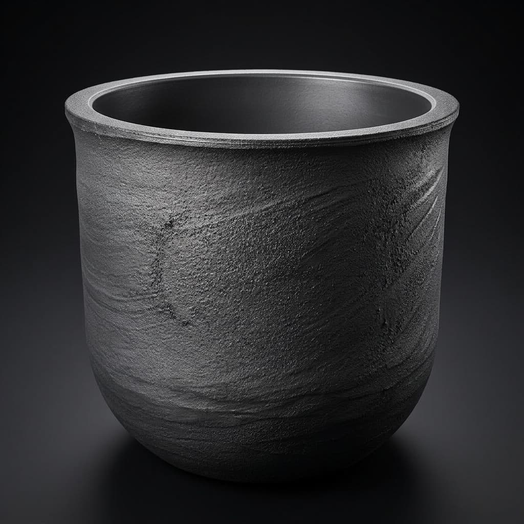
Induction Heating Skin Depth and Crucible Wall Thickness in SiC PVT: Electromagnetic Coupling, Thermal Gradients, and DFM Guidelines
Calculate induction heating skin depth for SiC PVT crucible walls, compare thermal trade-offs, and prepare graphite specifications for a drawing-based RFQ.
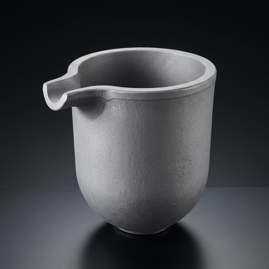
SiC PVT Seed Holder and Lid Assembly: Backside Sublimation Protection, CTE Mismatch, and Thermal Contact Conductance
Compare SiC PVT seed holder and lid assembly options, backside barriers, CTE clearance, and thermal contact conductance. Prepare a drawing-based technical RFQ.
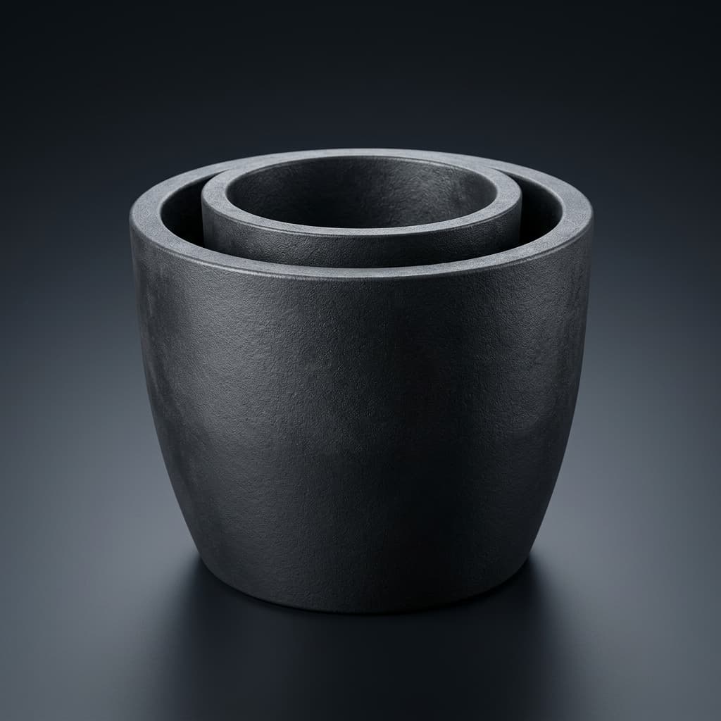
Vacuum Pre-Baking and Outgassing Protocols for SiC PVT Graphite Crucibles
Qualify vacuum pre-baking for SiC PVT graphite crucibles with RGA checks, supplier evidence, handling limits, and a practical engineering procurement checklist.