
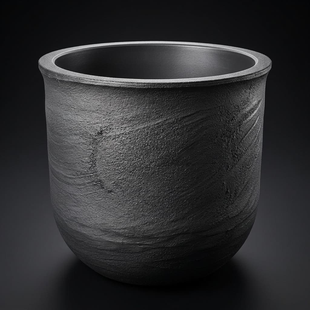
Induction Heating Skin Depth and Crucible Wall Thickness in SiC PVT: Electromagnetic Coupling, Thermal Gradients, and DFM Guidelines
Calculate induction heating skin depth for SiC PVT crucible walls, compare thermal trade-offs, and prepare graphite specifications for a drawing-based RFQ.
Induction heating skin depth helps engineers compare graphite crucible wall thickness with the distance over which alternating current penetrates the susceptor. In silicon carbide (SiC) Physical Vapor Transport (PVT) growth, that comparison connects material resistivity, generator frequency, heat deposition, and the geometry sent to a machining supplier. Skin depth alone cannot determine an approved wall thickness, crystal yield, or replacement interval.
For a quick screening example, assume non-magnetic graphite with electrical resistivity of 16 µΩ·m at the temperature being evaluated. Skin depth is 16.44 mm at 15 kHz and 10.76 mm at 35 kHz. An 18 mm wall therefore has thickness-to-skin-depth ratios of 1.10 and 1.67 respectively. These calculated ratios identify cases to simulate; they are not furnace acceptance limits.
Preparing an RFQ for custom-machined PVT crucibles? Submit drawings, operating frequency, and graphite grade data for DFM review.
Scope, Assumptions, and Engineering Boundaries
Published and updated on November 9, 2026. This guide is for global engineering and procurement teams specifying cylindrical isostatic graphite crucibles and susceptor assemblies, particularly for 150 mm and 200 mm SiC growth programs. Dimensions refer to crucible geometry; a nominal boule diameter does not establish a crucible bore or wall size.
The examples use an illustrative PVT temperature envelope of 2,100–2,400°C and non-magnetic graphite with relative permeability approximately one. The frequency matrix deliberately extends from 5 to 100 kHz to show sensitivity, rather than claiming every frequency suits a particular furnace size. Actual pressure, atmosphere, coil current, insulation, cooling, and charge properties must come from the qualified process.
Evidence boundary: numerical tables and wear examples below are reproducible calculations using stated inputs, not measured furnace runs or customer case studies. Assumed resistivity values are not certified grade properties. The cited literature supports thermal-field modeling and material-characterization principles; it does not establish universal wall ratios, machining tolerances, service lives, or supplier guarantees.
For related specifications, see 8-inch SiC crucible procurement, seed holder and lid assembly engineering, graphite crucible degradation mechanisms, porous graphite deflector plates, and vacuum pre-baking and outgassing protocols.
Executive Summary: Key Engineering Takeaways
- Use temperature-dependent resistivity. A room-temperature certificate establishes an incoming material check. It cannot replace the electrical-property curve required for a hot-zone model.
- Treat skin depth as a screening length. Increasing frequency decreases penetration; increasing resistivity increases penetration. Neither change independently establishes total absorbed power or the growth-interface shape.
- Evaluate electromagnetic and thermal behavior together. Thicker walls change current distribution, radial conduction, mass, and support geometry. The optimum depends on the complete furnace assembly.
- Track local wear rather than promising a run count. Inspect remaining wall thickness, threads, joints, coatings, and cracks against a process-qualified retirement rule.
- Make RFQ criteria measurable. Specify grade identity, test method, datums, inspection locations, and agreed acceptance limits instead of copying generic precision or purity numbers.
First-Principles Physics: Electromagnetic Induction in Graphite Susceptors
An alternating coil field induces electric fields and circulating eddy currents in a conductive graphite assembly. Resistive losses produce heat. For a homogeneous, non-magnetic good conductor under a locally planar approximation, skin depth is:
δ = sqrt(ρe / (π × f × μ0 × μr))
Here δ is in meters, ρe is electrical resistivity in Ω·m, f is frequency in Hz, μ0 is approximately 1.2566 × 10⁻⁶ H/m, and μr is relative magnetic permeability. With μr approximately one, a convenient unit-specific form is:
δ [mm] = 503.29 × sqrt(ρe [µΩ·m] / f [Hz])
For example, using 16 µΩ·m and 15,000 Hz gives 503.29 × sqrt(16 / 15,000) = 16.44 mm. Convert kHz to Hz before calculation. Also check resistivity units: 1 µΩ·m equals 100 µΩ·cm. Confusing these units changes the calculated depth by a factor of ten.
Current Decay and Volumetric Power Dissipation
In the semi-infinite planar model, current-density amplitude follows J(x) = J0 × exp(−x/δ). At one skin depth it is 36.8% of its surface amplitude. Using RMS current density, local Joule heating is q(x) = ρe × J(x)², so heat generation decays as exp(−2x/δ). Peak-amplitude current would introduce a factor of one half in time-averaged power; the normalized decay remains the same.
Integrating through the ideal conductor gives P(0 to x) / P(0 to infinity) = 1 − exp(−2x/δ):
- At 0.5δ: 63.2% of the semi-infinite reference power.
- At 1.0δ: 86.5%.
- At 1.5δ: 95.0%.
- At 2.0δ: 98.2%.
These fractions describe a particular reference field solution. They do not measure furnace efficiency or the percentage of magnetic flux blocked by a hollow crucible. A finite cylindrical wall has inner and outer electromagnetic boundary conditions; a lid, base, sleeve, conductive charge, and nearby insulation can change the solution. Use a coupled field model when curvature, joints, or additional conductive layers matter.
Induction Heating and Skin Depth Architecture
The diagram separates current amplitude from heat generation and shows the direction of inward heat transfer. It is schematic, not a furnace drawing or a measured thermal map. On narrow screens, scroll horizontally to read the labels.
High-Temperature Electrical Resistivity: Use Grade Data
Room-temperature resistivity is useful for incoming inspection, but operational skin depth requires resistivity at the temperature being modeled. The Entegris/POCO Graphite Properties and Characteristics primer, electrical-resistivity section, printed pages 24–25 describes a decrease toward approximately 700°C followed by an increase for the graphites discussed. That qualitative behavior is not a universal numerical correction for every isostatic grade.
Request the supplier's temperature-dependent curve, measurement direction, uncertainty, and applicable temperature interval. If validated hot data are unavailable, bracket plausible values as a sensitivity study and flag the material model as unresolved. Do not relabel a room-temperature certificate as evidence for 2,300°C properties.
Worked Sensitivity Calculation
Assume, solely for illustration, that a grade has resistivity of 11.0 µΩ·m at room temperature and 16.5 µΩ·m at a selected hot condition. At unchanged frequency:
δhot / δroom = sqrt(16.5 / 11.0) = 1.225
The assumed hot skin depth is 22.5% larger. At 15 kHz, those inputs give 13.63 mm and 16.69 mm. An 18 mm wall changes from a ratio of 1.32 to 1.08. This is a material-model sensitivity result, not proof of powder overheating or a rejected design. Record which input values are measured, supplier-provided, extrapolated, or assumed before approving the model.
For small changes at fixed frequency, a ±5% resistivity variation produces approximately ±2.5% variation in skin depth. A proposed ±5% lot window is a purchaser-supplier agreement, not an ASTM C611 acceptance requirement. Its value depends on the process sensitivity and the uncertainty of the measurement.
Skin Depth Matrix Across Frequency and Resistivity
Each cell below is calculated from the stated equation with μr = 1. Frequencies are converted to Hz, resistivity is in µΩ·m, and results are rounded to two decimals. The resistivity columns are independent inputs with no assigned temperature or grade. The final column uses an assumed 18 mm wall and the 16 µΩ·m column.
| RF frequency | δ at 10 µΩ·m | δ at 16 µΩ·m | δ at 18 µΩ·m | 18 mm wall / δ at 16 µΩ·m |
|---|---|---|---|---|
| 5 kHz | 22.51 mm | 28.47 mm | 30.20 mm | 0.63 |
| 10 kHz | 15.92 mm | 20.13 mm | 21.35 mm | 0.89 |
| 15 kHz | 12.99 mm | 16.44 mm | 17.43 mm | 1.10 |
| 25 kHz | 10.07 mm | 12.73 mm | 13.50 mm | 1.41 |
| 35 kHz | 8.51 mm | 10.76 mm | 11.41 mm | 1.67 |
| 50 kHz | 7.12 mm | 9.00 mm | 9.55 mm | 2.00 |
| 100 kHz | 5.03 mm | 6.37 mm | 6.75 mm | 2.83 |
At the same resistivity, doubling frequency reduces skin depth by a factor of sqrt(2). The matrix does not specify which frequency is common, optimal, or available for a given boule diameter. Check the generator's load range and matching network before treating any row as a feasible operating point.
Crucible Wall Architectures: Engineering Trade-Offs
Compare candidate architectures using the same coil boundary conditions, charge state, material curves, and thermal targets. No configuration below has a guaranteed lifetime or a universally optimum thickness ratio.
| Architecture | Potential benefit | Principal trade-off | Evidence needed before selection |
|---|---|---|---|
| Thin monolithic wall, tw below δ | Lower graphite mass; greater field penetration | Finite-wall coupling and mechanical margin need evaluation | Coupled field solution, stress assessment, and wear limits |
| Intermediate monolithic wall, tw near δ to 2δ | Useful range for comparing candidate designs | Ratio alone does not determine total absorbed power | Power balance, temperature profile, and transient response |
| Thick monolithic wall, tw above 2δ | More material for support or wear allowance | Additional conduction distance and thermal mass | Thermal resistance, support loads, and ramp analysis |
| Axially tapered wall | Adds a geometric variable for thermal-field adjustment | Taper also changes current paths and inspection access | Axial power map, smooth transitions, and machinable datums |
| Susceptor sleeve with replaceable liner | Separates some structural and chemical functions | Gaps, contact resistance, and multiple conductive layers | Assembly clearances, contact model, and replacement procedure |
| TaC-coated graphite wall | Candidate chemical barrier where qualified | Coating integrity and electromagnetic contribution require review | Thickness map, coverage, adhesion, and service records |
Scaling to 200 mm: Thermal Gradients and DFM Decisions
A larger boule target usually requires reassessing the complete hot zone. If a cylindrical bore increases from 180 to 250 mm at unchanged height, its internal volume increases by (250/180)² − 1, approximately 93%. Sidewall area rises by approximately 39%. These are geometry calculations, not a prediction of required generator power; wall dimensions, radiation, charge loading, and insulation also change.
Radial Conduction and Thermal Response
For a hollow cylinder without internal heat generation, constant conductivity gives the radial thermal resistance:
Rwall = ln(router / rinner) / (2 × π × k × L)
Use radii and heated length L in meters and conductivity k in W/(m·K). For an illustrative inner radius of 120 mm, changing the wall from 15 to 25 mm increases the logarithmic resistance term by approximately 61%, assuming unchanged k and L. It does not establish an outer-wall temperature or a source-to-seed gradient. Real induction heating is distributed within the wall, so the full thermal model must include that source distribution, radiation, and temperature-dependent conductivity.
Evaluate both steady operation and ramps. Compare the source and seed temperatures, axial and radial gradients, outer-wall temperature, coil power demand, and response to a controlled power change. Zhang et al.'s 8-inch SiC PVT thermal-field study provides application-specific modeling context; its findings do not qualify a different furnace or machining drawing.
Wall Uniformity, Datums, and Inspection
Eccentricity changes local thickness and therefore electromagnetic and thermal behavior. The direction and magnitude of the temperature change depend on the field solution and boundary conditions. A universal statement that the thicker side always becomes hotter, or that a specified runout causes a fixed crystal tilt, is not justified.
Define the mounting datum, bore axis, outside-surface control, and the locations used to calculate minimum remaining thickness. Concentricity and total runout describe different geometric controls; choose the required control explicitly on the drawing. Agree a tolerance based on process sensitivity, component size, graphite grade, metrology uncertainty, and machining capability. Tightening every dimension increases cost without necessarily controlling the important hot-zone variables.
Wall Thinning and a Reproducible Wear Example
Chemical attack and handling damage can change the wall profile over repeated campaigns. Obtain local wear measurements from the actual process rather than converting a generic corrosion rate into a service-life promise.
For an arithmetic example only, assume an initial 18.0 mm wall and a uniform loss of 0.30 mm per completed campaign. At 15 kHz with assumed resistivity of 16.0 µΩ·m, δ is 16.44 mm. After two campaigns, the wall is 17.4 mm and its ratio is 1.06; after four, it is 16.8 mm and its ratio is 1.02. These are hypothetical dimensions, with no measured growth outcome or retirement decision attached. Crossing tw/δ = 1 is not a physical on/off threshold.
If a qualified process instead specifies a local retirement thickness of 16.0 mm and an additional inspection reserve of 0.5 mm, the illustrative usable allowance is 18.0 − 16.0 − 0.5 = 1.5 mm. At the assumed uniform loss, that is five campaigns to reach the reserve boundary. It does not authorize five runs: local pits, cracks, threads, coating damage, or measurement uncertainty may require earlier retirement.
Product Context and Material Selection
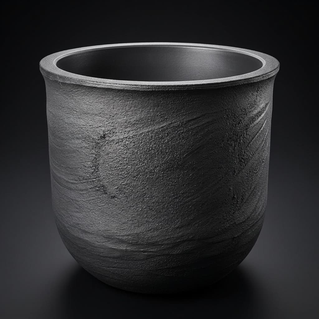
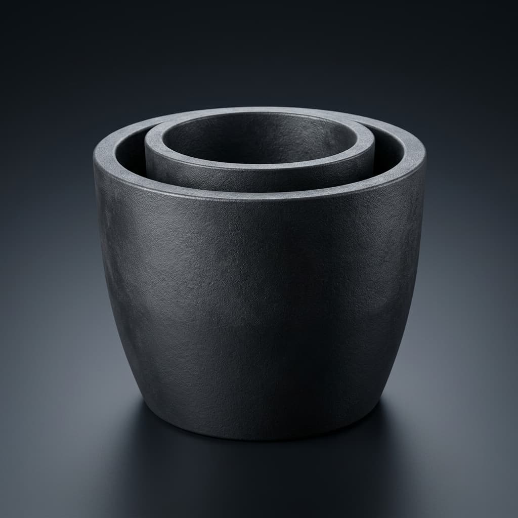
Product illustration for reviewing body, lid, and assembly geometry. A photograph cannot verify graphite grain size, purity, electrical resistivity, dimensional capability, or service life; request the relevant inspection records.
Compare electrical and mechanical properties on the same identified grade and lot. Density, pore structure, resistivity, thermal conductivity, expansion, strength, and impurity content answer different questions. A higher density or a low total ash value cannot independently certify the required hot resistivity or an element-specific contamination limit.
The ASTM C611 official scope addresses electrical resistivity of manufactured carbon and graphite at room temperature. Ask for specimen geometry, orientation, test temperature, results, and the cited method edition. Specify any hot-property testing separately, including its atmosphere and uncertainty. For coatings, also request the coated surface map and agreement on whether dimensional inspection occurs before or after deposition.
Compare the SiC crystal growth crucible product scope with the precision graphite machining DFM workflow. Send the dimensions and evidence requirements together so the quote reflects the actual acceptance plan.
Engineering and Procurement Checklist for Wall Sizing
Before releasing drawings or purchase orders, close the following ten items with the furnace owner and supplier:
- 1. Frequency and load: Record the operating frequency range, matching limits, and coil conditions used in the model, including startup and full-load conditions.
- 2. Material model: Identify the graphite grade, orientation, temperature-dependent resistivity and conductivity, and any assumed or extrapolated values.
- 3. Lot acceptance: Agree the room-temperature test method, sampling plan, measurement uncertainty, and numerical acceptance window. Keep it separate from hot-property qualification.
- 4. Geometry and datums: Specify ID, OD, minimum wall thickness, datum scheme, runout control, and measurement locations rather than relying on a nominal wall dimension alone.
- 5. Tapers and transitions: Review blend radii, tool access, threads, and thickness transitions with the machinist and modeler. Release radii through the drawing rather than a generic article rule.
- 6. Wear allowance: Derive the sacrificial allowance and inspection reserve from local process wear data and a qualified retirement profile.
- 7. Structural interfaces: Check the base, lid, supports, thread engagement, assembly clearances, and handling loads alongside the heated wall.
- 8. Surface condition: Agree roughness and edge criteria by functional surface, the measurement method, and chip or crack rejection criteria.
- 9. Purity and coatings: Specify required impurity elements, analytical method, reporting limits, coating coverage, and evidence of coating integrity. Total ash alone is insufficient.
- 10. Cleaning and release: Agree purification, pre-baking, packaging, traceability, and incoming inspection. Qualify the treatment recipe for the grade and coating instead of prescribing a universal bake temperature.
Frequently Asked Questions
How does induction frequency affect the required crucible wall thickness?
At unchanged resistivity, skin depth varies as the inverse square root of frequency. With the assumed 16 µΩ·m input, it is 20.13 mm at 10 kHz and 10.76 mm at 35 kHz. This comparison helps select model cases. Mechanical support, thermal gradients, wear allowance, and generator compatibility still determine the acceptable wall geometry.
Can we compensate for wall thinning by tuning induction frequency?
Holding tw/δ constant at unchanged resistivity requires frequency to scale inversely with wall thickness squared. Thinning from 18 to 16 mm would require a factor of (18/16)² = 1.266, or approximately 19.0 kHz instead of 15 kHz. That arithmetic does not establish equivalent furnace behavior. Changing frequency affects impedance, current distribution, and other conductive parts; use an equipment-approved setting and requalify the thermal response.
What happens if the wall is thinner than one skin depth?
Field penetration becomes more relevant, and a semi-infinite wall approximation becomes less reliable. Actual charge heating depends on charge conductivity, packing, geometry, frequency, and temperature. A ratio below one does not automatically predict parasitic heating, a particular polytype, or crystal rejection. Model the complete assembly and compare with qualified temperature and growth measurements.
Why does wall eccentricity matter for thermal uniformity?
It changes the local current distribution and heat-transfer path around the circumference. However, thickness variation alone cannot predict a temperature difference or crystal tilt. Control geometric datums and map wall thickness, then evaluate the measured geometry in the furnace model before assigning a tolerance or diagnosing a growth defect.
Does TaC coating eliminate the need to calculate skin depth?
No. A chemical barrier does not remove the need to model the graphite susceptor. Whether a conductive coating can be neglected electromagnetically depends on its thickness, conductivity, continuity, and frequency, rather than its thickness alone. A qualified intact coating may reduce attack, but it does not guarantee zero wall loss or an unchanged thermal field across campaigns.
Can bulk density substitute for a resistivity certificate?
No. Density can help characterize a graphite grade, but microstructure, processing, orientation, and temperature also affect electrical behavior. Require the specified electrical test and traceability to the supplied grade or lot. A density specification is not a substitute for a hot-property curve or a batch acceptance result.
How should crucibles be inspected between campaigns?
Map local wall thickness using accessible dimensional or scanning methods with demonstrated uncertainty. Compare the same heights and azimuths with the previous inspection; include the base, threads, joints, and coating condition. Any ultrasonic method needs calibration for the actual graphite and surface condition. Track mass as a supporting trend, but use local damage and qualified acceptance limits for retirement decisions. No universal mass-loss percentage or tw/δ cutoff applies to every hot zone.
Sources and References
- Zhang, S., et al. (2023). Design and Optimization of Thermal Field for PVT Method 8-Inch SiC Crystal Growth. Materials, 16(2), 767. Application-specific thermal-field modeling context, not a universal wall-thickness standard.
- ASTM International, C611-21. Standard Test Method for Electrical Resistivity of Manufactured Carbon and Graphite Articles at Room Temperature. Public scope and method identification; it does not prescribe the RFQ acceptance window used in this guide.
- Entegris/POCO. Graphite Properties and Characteristics, electrical-resistivity section, printed pages 24–25. Manufacturer reference for material testing and temperature dependence; grade-specific hot values still require their own evidence.
Technical Inquiry and RFQ Engineering Support
For a new hot zone or a change from 150 mm to 200 mm growth, prepare the body, lid, liner, and support drawings as one package. Include the graphite grade, coil frequency range, temperature envelope, coating map, forecast quantity, and inspection requirements. Mark unresolved hot-property data so the engineering review can distinguish machining feasibility from furnace-process qualification.
Submit drawings and material requirements for engineering review, or review the SiC PVT crystal growth solution scope. Request confirmation of achievable tolerances, certificate scope, and qualification responsibilities in the quotation; final crystal performance and replacement intervals require validation in your furnace.
Author

Categories
More Posts
CVD TaC Coating Failure Modes in SiC PVT: Delamination Mechanics, Silicon Vapor Infiltration, and Substrate DFM Standards
Diagnose CVD TaC coating failure in SiC PVT: compare delamination, vapor ingress and graphite DFM risks, then prepare a drawing review and supplier RFQ.
SiC PVT Seed Holder and Lid Assembly: Backside Sublimation Protection, CTE Mismatch, and Thermal Contact Conductance
Compare SiC PVT seed holder and lid assembly options, backside barriers, CTE clearance, and thermal contact conductance. Prepare a drawing-based technical RFQ.
Vacuum Pre-Baking and Outgassing Protocols for SiC PVT Graphite Crucibles
Qualify vacuum pre-baking for SiC PVT graphite crucibles with RGA checks, supplier evidence, handling limits, and a practical engineering procurement checklist.